Scooter DI
BLASI mod. R30
SERVICE MANUAL
(Ed.
INDEX
A) MAINTENANCE
A.1) Monthly checks
B.1) General notices concerning
electric failures
B.2) The traction motor runs
irregularly
B.4) The scooter cannot be
unfolded
B.5) While the scooter is unfolded and when pressing the main yellow
button, a beep is audible
B.6) While the scooter is unfolded and when pressing the main yellow
button, no LED lit on control panel
B.7) The control panel at the
handlebar does lit but the scooter does not run
B.8) At the end of unfolding step a long beep is audible and the control
panel does not lit
B.9) The scooter can be folded but cannot be unfolded
B.10) The scooter can be unfolded but cannot be folded
B.11) The scooter does not run backwards
C) OPERATIONS
C.1) Wheel+Brake Assembly
replacement
C.2) Brake Assembly replacement
C.3) Handlebar folding control
cable replacement
C.4) Scooter Controller
replacement
C.5) Motor Controller
replacement
C.6) Battery support replacement
C.7) Folding-unfolding stop
switches adjustments
C.8) Folding/unfolding buttons
replacement
C.9) Front fork returning spring
replacement
C.10) Handlebar returning spring
replacement
C.11) RH loom (pn 3135) and LH
loom (pn 3149) replacement
C.12) Motor-controller loom (pn
3098) replacement
C.13) Gears assembly (pn
3582+pn3583) replacement
C.14) Geared rod (LH side) (pn
3595) replacement
C.15) Geared rod (RH side) (pn 3594)
replacement
C.16) Seat sheet (pn 3021)
replacement (Versions until 31-12-2016)
C.17) Seat sheet (pn 3021)
replacement (Versions from 01-01-2017)
C.18) Cancelling the reverse speed
sound (beep) warning
A.1.a) Apply a few drops of light oil on all mechanical joints and in the gears
of the folding mechanism.
A.1.b) All nuts and bolts are equipped with locking devices (lock nuts, self
locking nuts, lock washers, thread lock liquid, etc), nevertheless check their
tightening.
B.1) General notices concerning electric
failures
In the sections of this manual
concerning the electric failures, the following definitions apply:
B.1.a)
A battery is
in good order when:
B.1.a.1)
The tension
at its terminals is not less then 25,6V
B.1.a.2)
Charging
time of a completely empty battery, when it is a new one, is about 4 hours.
However, more the battery is old, less is its capacity to take charge so that
the charging time reduces.
B.1.a.3)
The
terminals of the battery are not rusty or dirty: this would reveal bad quality
of contact at these terminals.
B.1.b)
Integrity of
a loom means that:
B.1.b.1)
Each of its
wires is firmly connected to the corresponding male/female connector at its ends
and each of these connectors is firmly connected to the corresponding
female/male connector of the corresponding device.
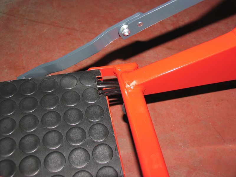
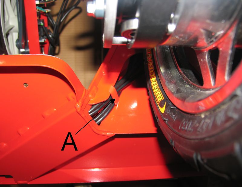
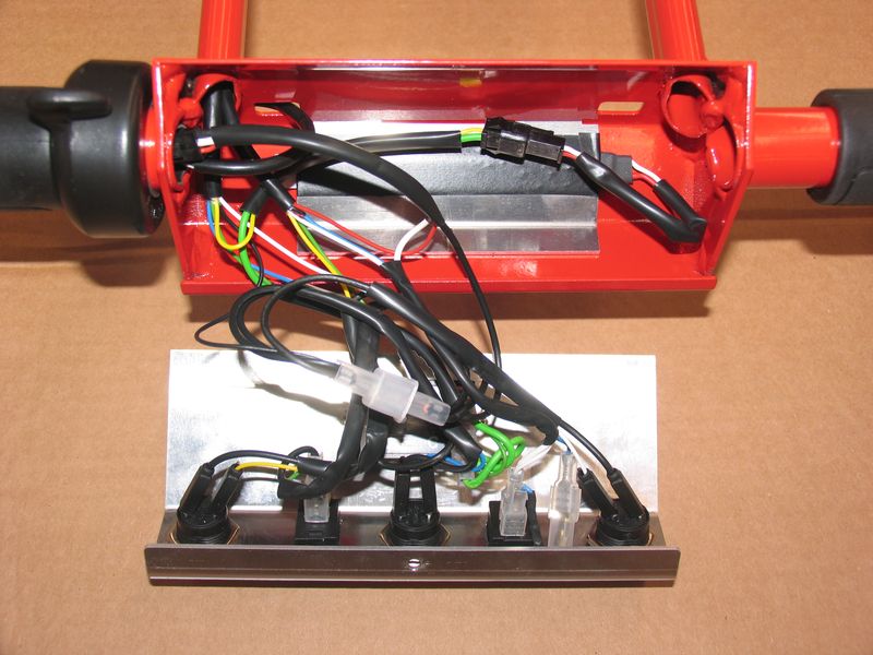
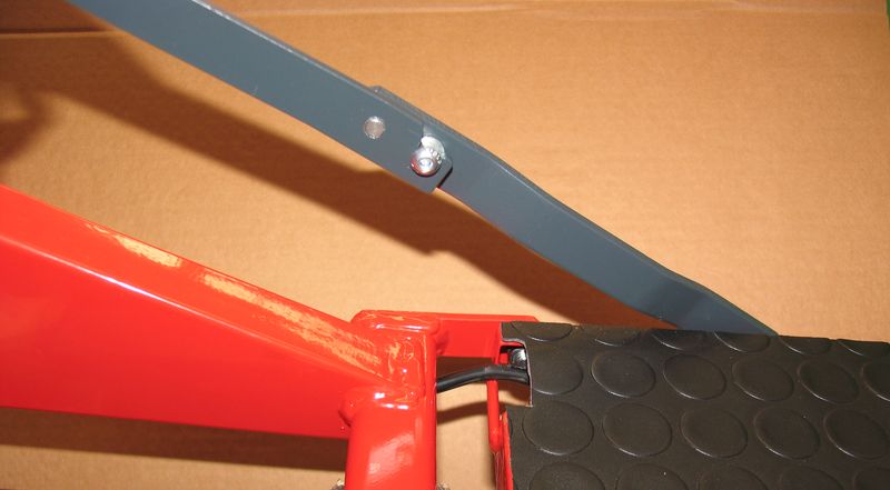
B.1.b.1)
There are no
visible damages, especially in tracts corresponding to the hinges between
footboard and main frame (Pic B1.1 + Pic B1.2) and to the handlebar hinge (Pic B1.3).
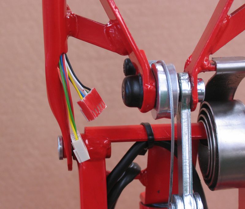
B.1.b.2)
There is
electric continuity in each of its wire. A multimeter allows to detect any
steady discontinuity. But sometime a broken wire allows an unsteady electric
continuity. To detect such case of failure, raise the front wheel of the
scooter from the ground and while pressing the speed control lever move
slightly in all directions each cable mainly in the tracts corresponding to the
hinges between footboard and main frame (Pic B1.1 + Pic B1.2) and to the
handlebar hinge (Pic B1.3): while moving each
cable check if any irregularity of the motor. Any irregularity reveals that an
internal wire is broken in that point.
B.2) The traction motor runs irregularly
B.2.a)
Check
integrity of the looms (See Sec. B.1.b)
B.2.b)
Carry out
the following:
B.2.b.1)
Activate the
main switch
B.2.b.2)
Raise the front
wheel from the ground
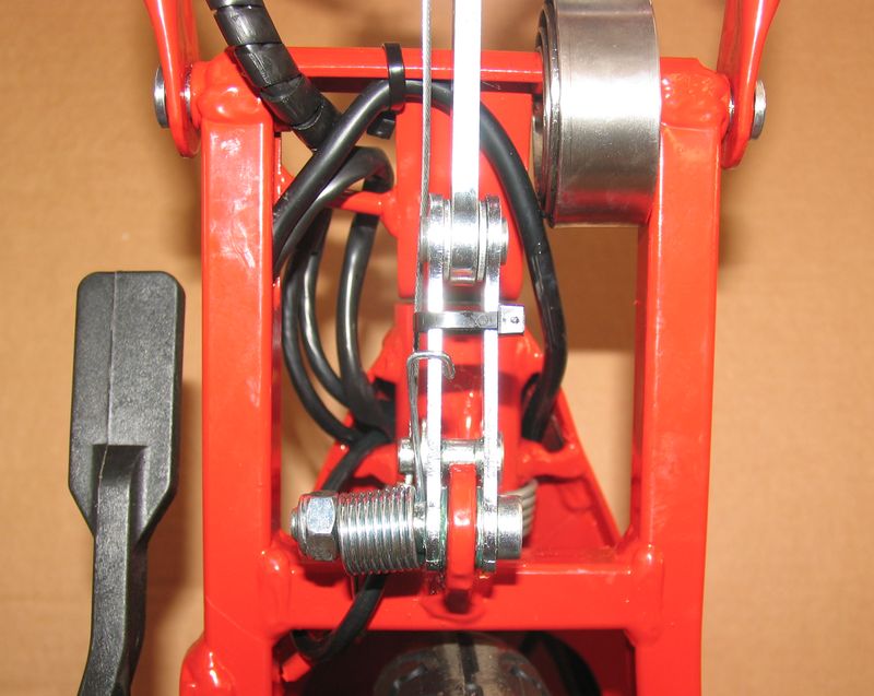
B.2.b.3)
While
pressing the speed control lever, move slightly in all directions the cable
entering in the motor shaft (W – Pic B2.1) and
observe if any irregularity in the motor running. If any irregularity, replace
the motor
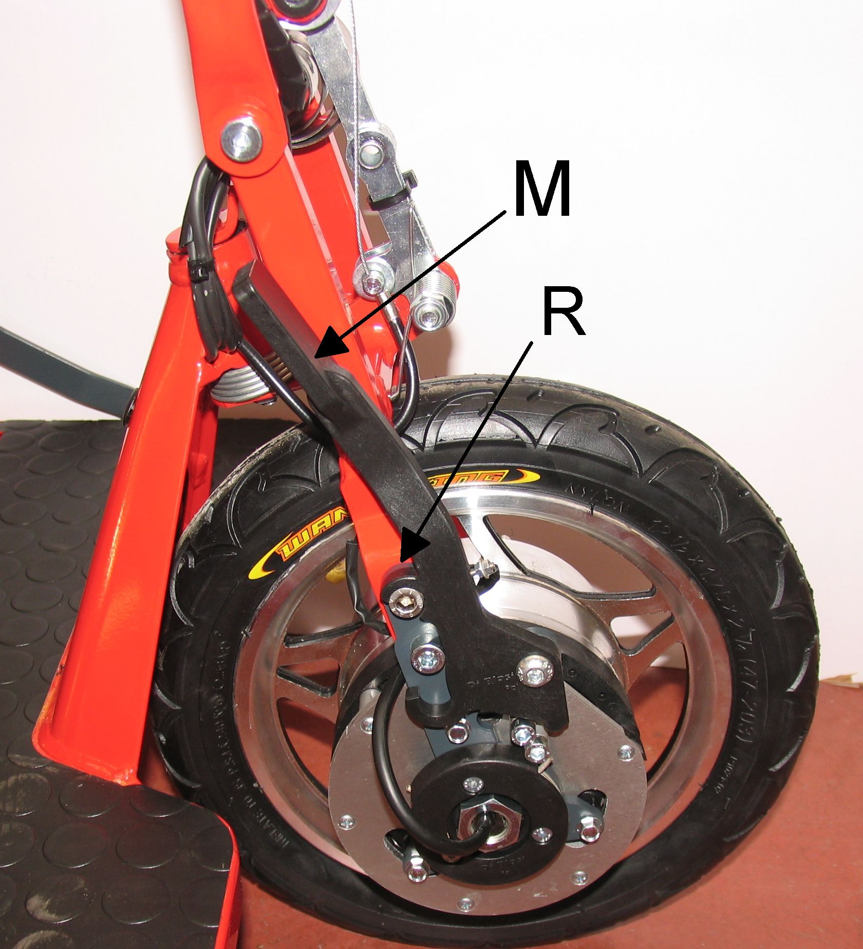
B.3) The brake does not work
(The scooter does not stop as soon as the speed control lever is released or
the scooter stays in free ride mode also when the brake disconnecting lever (M)
is locked by the hook (R) in the position
shown in Pic B3.2 (see also Sec 4.3.d) in
the Owner's Manual).
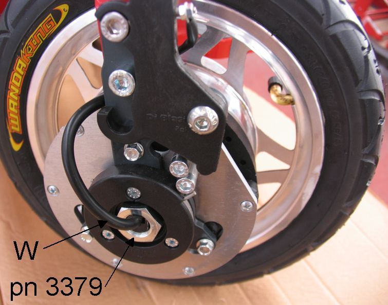
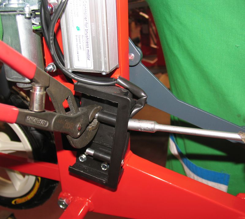
B.3.a)
Tighten the
nut (pn 3379) (Pic B3.1) after having added some drops of thread lock liquid
in its threads.
B.3.b)
If the nut
(pn 3379) (Pic B3.1) is tightened, disassemble
the brake and check if
B.3.b.1)
The brake
discs are broken or worn
B.3.b.2)
The plastic
guide of the steel discs are damaged (due to overheating, for instance)
B.3.b.3)
For
disassembling and assembling the brake assembly see Sec C.2
B.4) The scooter cannot be unfolded
B.4.a)
Check that
the brake disconnecting lever is (M) is firmly locked by the hook (R) in the
position shown in Pic B4.1 (see also Sec 4.3.d)
in the Owner's Manual).
B.4.b)
Check if a beep
is audible when inserting the battery:
B.4.b.1)
If no beep
is audible
· Check the tension at the terminals of the battery
support
*
If there is
no tension, replace the battery
*
If there is
tension
-Check the integrity of the loom (pn 3463) from the
battery support to connector (J1) at the scooter controller (see wiring diagram).
-If loom (pn 3463) is in good order replace the scooter
controller.
B.4.b.2)
If a beep is
audible: go to Sec B.4.c)
B.4.c)
Check if a beep
is audible when pushing the unfolding green button
B.4.c.1)
If a beep is
audible:
· Check if the unfolding stop switch is defective (see wiring diagram). If it is in good order ...
· ... check the integrity of the loom (pn 3410) (see wiring diagram). If it is in good order, then ...
· ... replace the scooter controller
B.4.c.2)
If no beep
is audible
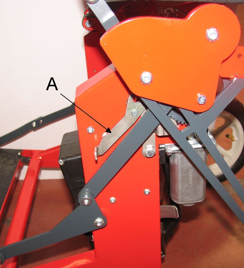
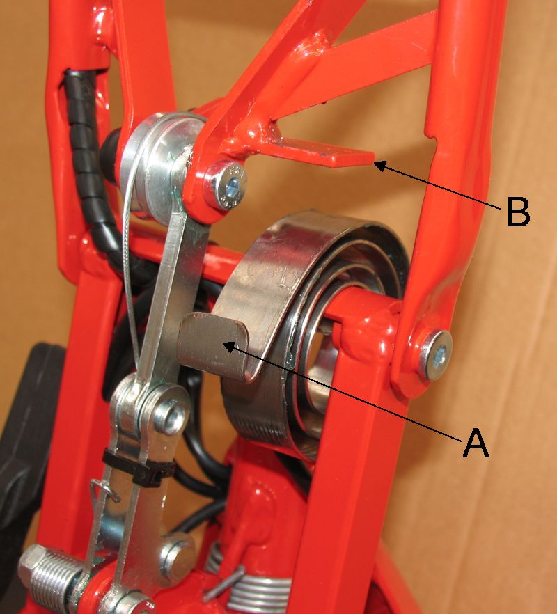
· Check if the lever (A) which connects/disconnects the
folding mechanism gears is firmly locked in the position shown in Pic B4.2 (in this position the folding-unfolding
mechanism gears are connected each other - See also Sec 2. - Par.
"Unfolding the scooter manually " in the Owner's Manual).
· Check the integrity of the loom (pn 4043) (see wiring diagram)
· Check the connection between connector (J2) on the
scooter controller and connectors (J18) and (J19) on the folding-unfolding
motor ( see wiring diagram). In particular check if, while pressing the
unfolding green button there is a tension of about 24V at connectors (J18) and
(J19)
*
If there is
tension, replace the motor
*
If there is
no tension, replace the scooter controller
B.5) While the scooter is unfolded and
when pressing the main yellow button, a beep is audible
B.5.a)
Check that
the brake disconnecting lever is (M) is firmly locked by the hook (R) in the
position shown in Pic B5.1 (see also Sec 4.3.d)
in the Owner's Manual).
B.5.b)
Press the
unfolding green button and check if a short beep or a long beep is audible.
B.5.b.1)
If a short
beep is audible
· Replace the scooter controller
B.5.b.2)
If a long
beep is audible
· Go to Sec B.8)
B.6) While the scooter is unfolded and
when pressing the main yellow button, no LED lit on control panel
B.6.a)
Disassemble
the control panel panel (pn 3553) (see Pic B6.1)
and check the integrity of the loom (pn 3149) (see wiring diagram). If it is in good order, then...
B.6.b)
.... check
that between the black wire and the green wire at the battery indicator there
is a tension of 24V
B.6.b.1)
If there is
tension: replace the indicator
B.6.b.2)
If there is
no tension: replace the scooter controller
B.7) The control panel at the handlebar
does lit but the scooter does not run
B.7.a)
Check the
integrity of the loom (pn 3135) (see wiring
diagram). If it is in good order,
then...
B.7.b)
... check at
loom (pn 3463) (see wiring
diagram) if at both ends of the red
wire connecting connector (J10) at the motor controller and the connector (J6)
at the scooter controller, there a tension of 24V
B.7.b.1)
If there is
no tension: replace the scooter controller
B.7.b.2)
If there is
tension: go to Sec. B.7.c)
B.7.c)
Press
progressively the speed control lever and check if at the end of the white wire
on the connector (J10) at motor controller there is a tension increasing
progressively up to about 5V
B.7.c.1)
If there is
tension
· check if the motor controller or the motor itself is
defective
B.7.c.2)
If there is
no tension
· Go to Sec. B.7.d)
B.7.d)
Check that
there is a tension of 5V at the end of the red wire at the connector (J22) on
the control panel:
B.7.d.1)
If there is
tension, press progressively the speed control lever and check if at the end of
the white wire on the same connector (J22) there is a tension increasing
progressively up to 5V
· If there is no tension
*
replace the
speed control lever (pn 4036)
B.7.d.2)
If there is
no tension at the end of the red wire at the connector (J22)
· Replace the scooter controller
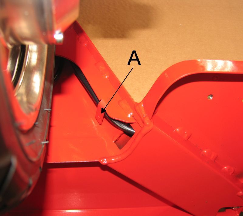
B.8) At the end of unfolding step a long
beep is audible and the control panel does not lit
B.8.a)
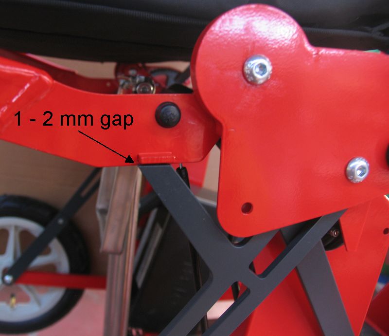
At the end
of unfolding step, the gap between the seat frame protrusion and the geared rod
is to be 1÷2 mm as shown in Pic
B8.1. If the scooter does not unfold completely,
this gap shall remain more than 1÷2 mm so that the unfolding stop switch (pn
4079 (A) - see Pic B8.2) shall not be activated and therefore the scooter
cannot run.
Check if the reason why the scooter does not unfold completely is due to some
jamming of the folding mechanism: for instance a loosen screw or nut, a cable
hanging somewhere, a broken gear in the folding mechanism, etc. To check more
easily if and where the folding mechanism jams, fold and unfold manually the
scooter (see Owner's Manual, Sec 2, last paragraph). If none jam occurs, then
...
B.8.b)
...anticipate
the unfolding stop switch (see Sec C.7 - 5th paragraph - “To anticipate
unfolding stop”).
B.9) The scooter can be folded but cannot
be unfolded
B.9.a)
Check if, when
pressing the unfolding green button, a short beep is audible
B.9.a.1)
If a beep is
audible:
· Check integrity of loom (pn 3410) (see wiring diagram). If i is in good order, then ...
· ... check the unfolding stop switch (pn 4079(A) - Pic B9.1). If in good order, then ...
· ... replace the scooter controller
B.9.a.2)
If no beep
is audible:
· Checks integrity of
the folding/unfolding buttons loom (pn 4043) (see wiring diagram). If in good order, then ....
· ... disconnect the two parts of the connector J4 at
the scooter controller and while pressing the unfolding green button, check if
there is electric continuity between the green and black wires of the loom (pn
4043) (see wiring
diagram).
*
If no
continuity, replace the green button.
*
If there is
continuity, replace the scooter controller
B.10)
The scooter can be unfolded but cannot be folded
B.10.a)
Check if,
when pressing the folding red button, a short beep is audible
B.10.a.1)
If a beep is
audible:
· Check integrity of loom (pn 3410) (see wiring diagram). If it is in good order, then ...
· ... check the folding stop switch (pn 4079 (B) - Pic B10.1). If it is
in good order, then ...
· ... replace the scooter controller
B.10.a.2)
If no beep
is audible:
· Checks integrity of
the folding/unfolding buttons loom (pn 4043) (see wiring diagram). If it is in good order, then ...
· ... disconnect the two parts of the connector J4 at
the scooter controller and while pressing the folding red button, check if
there is electric continuity between the grey and black wires of the loom (pn
4043) (see wiring
diagram).
*
If no
continuity, replace the red button.
*
If there is
continuity, replace the scooter controller
B.11)
The scooter does not run backwards
The tests
described in this section are to be carried out while the scooter functions are
active, i.e. the scooter is not in stand-by mode.
B.11.a)
No beep is audible when the reversing speed
rocker switch is ON
- Remove the control panel on the top of the handlebar
- Check if the green and black wires are well
connected to the reversing speed rocker switch.
If they are in good order, then ...
- ... check if the rocker switch is in good order (you
can use a multimeter for this purpose).
If it is in good order then....
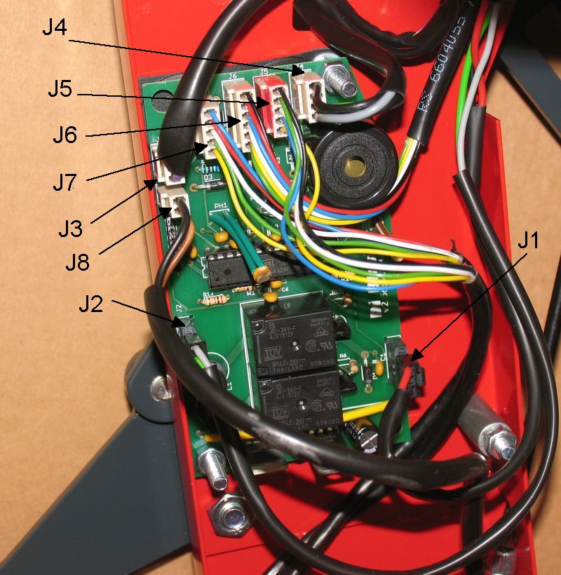
- remove the scooter controller cover on the RH side
of the scooter (See the first two paragraphs of Sec C.4) and check if the green wire is firmly connected to the
connector J7 of the scooter controller (Pic C4.4) (see wiring
diagram).
If the green wire is firmly connected,
then...
- ... use a multimeter to check if there is electric
continuity on the green wire from its connection to the rocker switch to the connector J7 of the scooter controller (Pic C4.4) (see wiring
diagram).
If there is continuity, replace the scooter controller
B.11.b)
A beep is audible when the reversing speed
rocker switch is ON
- Remove the scooter controller cover on the RH side
of the scooter (See the first two paragraphs of Sec C.4)
- Check if the blue wire is filmily connected to
connector J6 of the scooter controller (Pic C4.4) (see wiring
diagram). If it is in good order then....
- ... remove the motor controller cover on the LH side
of the scooter (See the first two paragraphs of Sec C.5) and check if the blue wire is filmily connected to connector J10 (see wiring diagram) of the motor controller.
If it is in
good order then....
- use a multimeter to check if there is electric
continuity at the blue wire between its
connection to the connector J6 (see wiring diagram) of the scooter controller and connector J10 (see wiring diagram) of the motor controller. If there is continuity ...
- ... use an
extra wire to connect the end of blue
wire at connector J10 of the motor controller at any point of the frame
(ground) or to the negative of the battery support and check if the reverse
speed works. If it does not work replace
the motor controller. If it works replace the scooter controller.
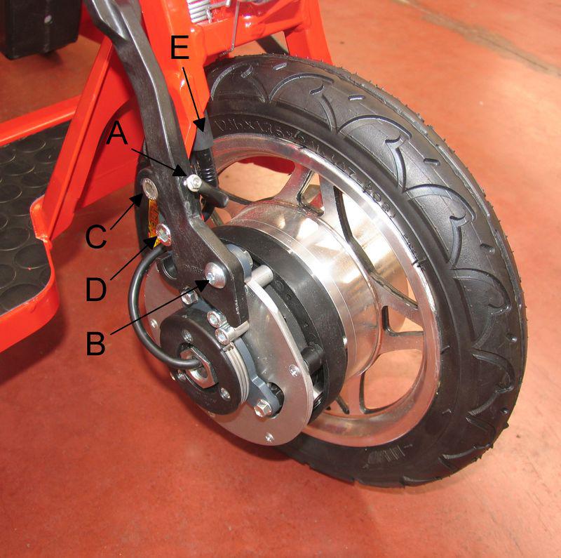
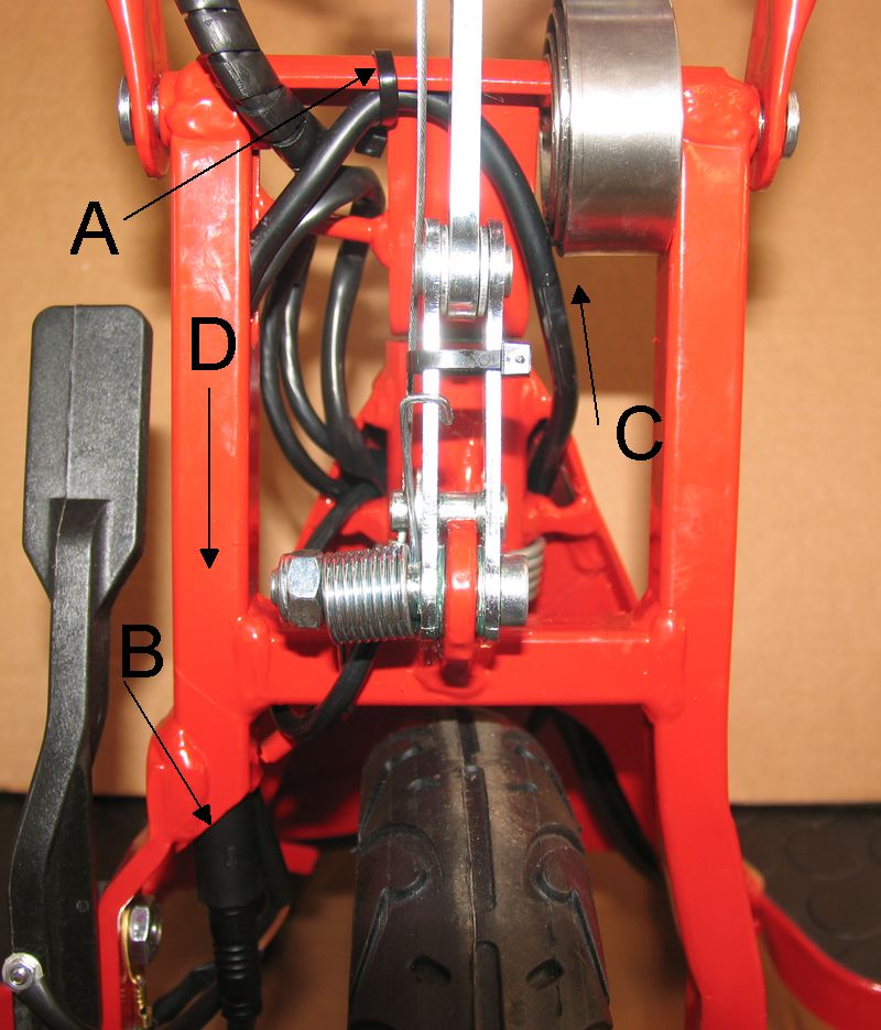
C.1) Wheel+Brake Assembly replacement (Pic C1.1)
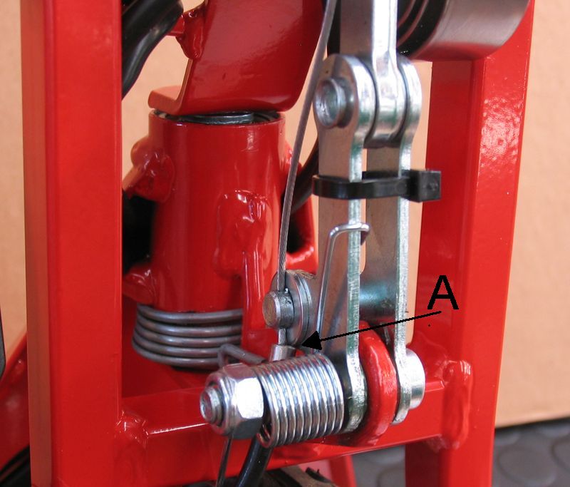
# Disconnect the cable (A) from the small screw fitted on the brake
disengaging lever;
# Unscrew the nut of the screw (B) and remove the screw (B)
# Unscrew the nut of the screw (C) and remove the screw (C) and the round
cable terminal below the nut
# Unscrew the screw (D)
# Remove the wheel from its LH seat
# Disconnect the two parts of the round connector (E). To avoid damage to
the connector do not disconnect them by pulling the relevant cables but by
pulling the two parts.
# Remove the wheel from the fork
# When reassembling the wheel+brake assembly on the scooter pay attention
to that:
* when connecting the two parts of the round connector (E), the two arrows
marked on each of the two parts have to correspond each other;
* do not forget to connect the cable (A) at the end of the small screw
fitted on the brake disengaging lever and make sure that the screw can move a
little bit along its seat in the lever so that the spring inside the seat can
push the small screw to certainly contact the screw (C) when the lever is
engaged as shown in Pic C1.1
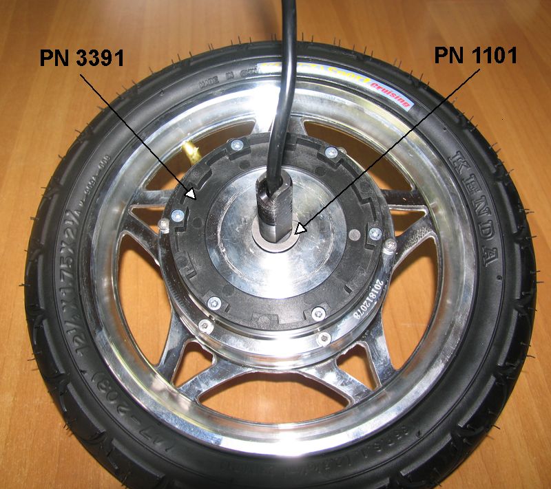
C.2) Brake Assembly replacement
(04/19)
# Pic C2.1b - Fit the brake turning disc
holder (PN 3391) on the wheel
# Pic C2.1b - Fit a first shim 16 x 24 thickness 1 mm (PN 1101)
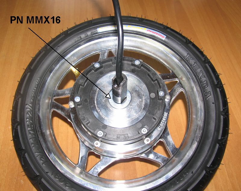
# Pic C2.2b - Fit the washer (PN MMX16)
thickness 2,5 mm on top of the first shim.
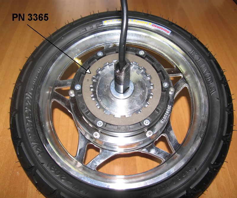
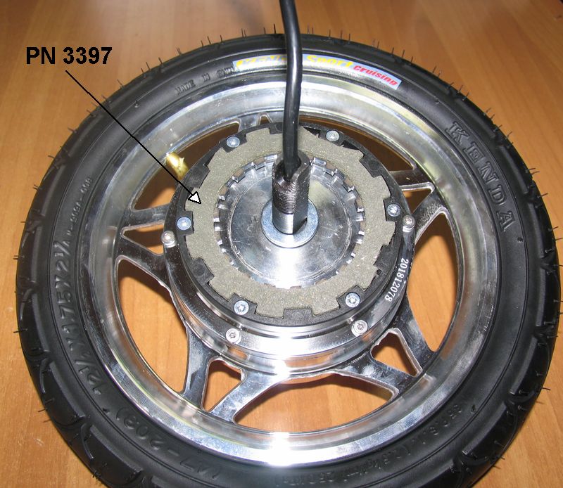
# Pic C2.3b - Fit the internal teeth steel
disc (PN 3365)
# Pic C2.4b - Fit the external teeth disc
(PN 3397) on top of the steel disc, so that its teeth engage the teeth of the
brake turning disc holder
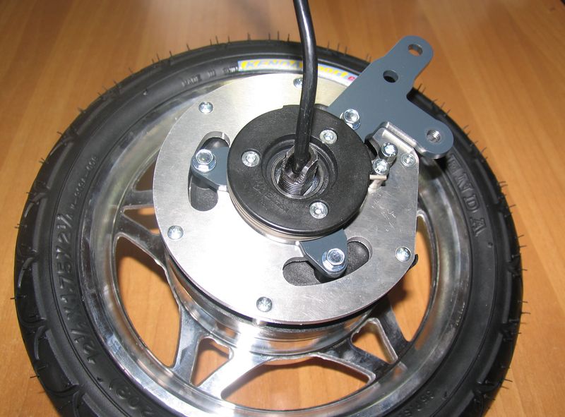
# Pic C2.5b - Fit the brake main body. For
an easier fitting move the brake main body slighly sideways so that its teeth
can more easily engage the teeth of the steel disc.
# Pic C2.6b - Screw and tighten the wheel
axle nut (PN 3379)
# Assemble the
wheel+brake assembly on the scooter and test the brake efficiency on the road:
* If braking is too
soft, disassemble the wheel+brake assembly from the scooter, replace the washer (PN MMX16) thickness 2,5 mm with a
washer 2,3 mm. If braking is still too soft, replace the washer 2,3 mm
thickness with a washer 2,2 mm
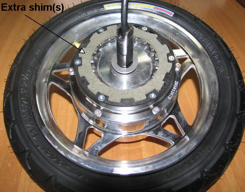
* If braking is too
abrupt, disassemble the wheel+brake assembly from the scooter and add a shim
thickness 3/10 mm on the top of the washer MMX16 (Pic
C2.7b) . If braking is still too abrupt add a second shim of 2/10 mm or
3/10 mm on the top of the first shim.
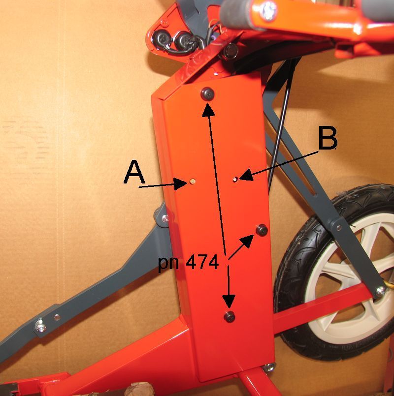
C.3) Handlebar folding control cable replacement
# Check that the scooter is completely unfolded.
# Pic C3.1 - Remove the 3 plastic caps (pn
474) on the RH side cover and the three nuts underneath
# Pic C3.2 - Remove the cover
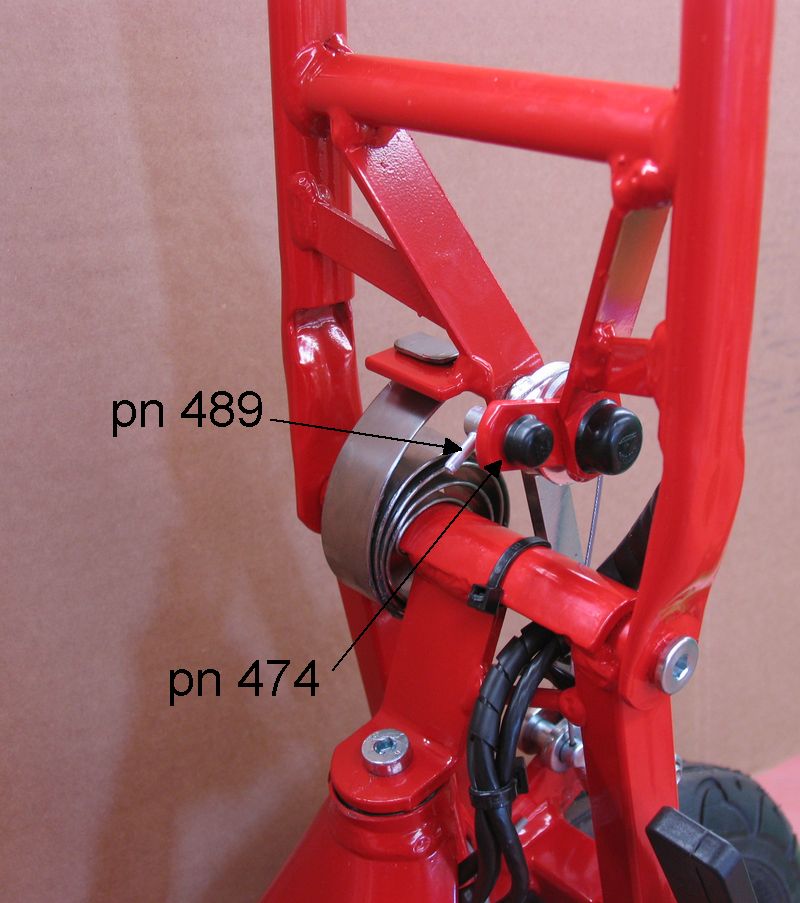
# Pic C3.3 - Remove the cap (pn 489) from
the end of the steel cable and the plastic cap (pn 474) from the clamp screw
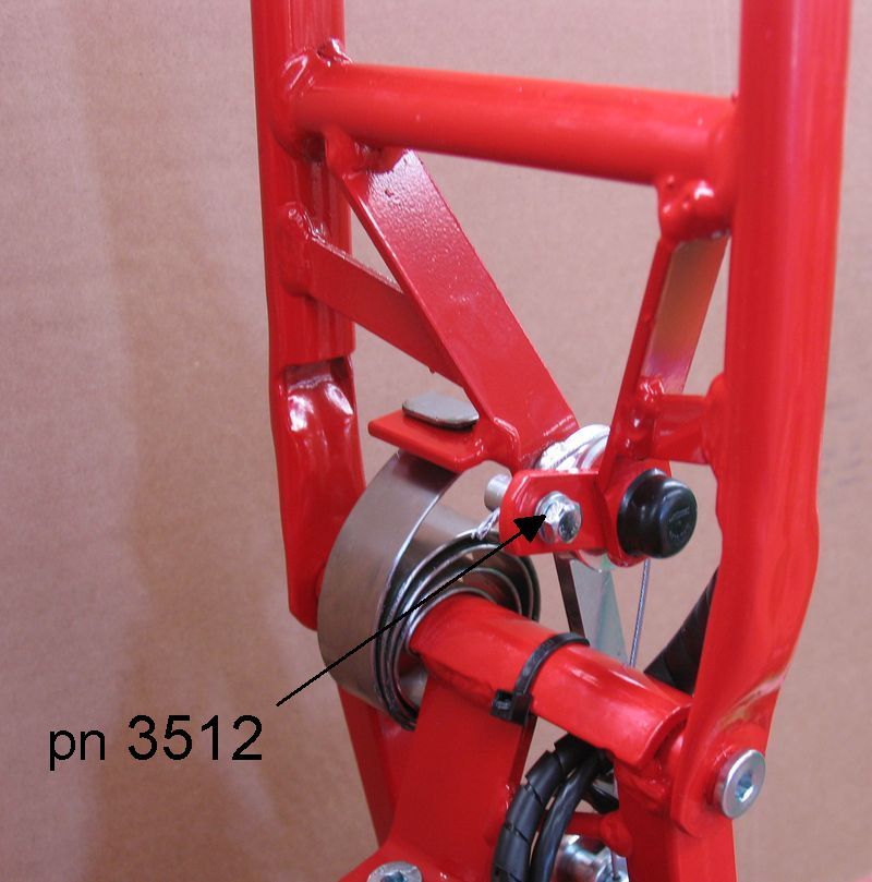
# Pic C3.4 - Loosen the cable clamp screw
(pn 3512)
# Pull out the cable from its rear end under the RH side of the seat
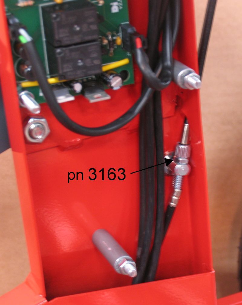
# Check that the adjustment device (pn 3163) is completely screwed on as
shown in Pic C3.5
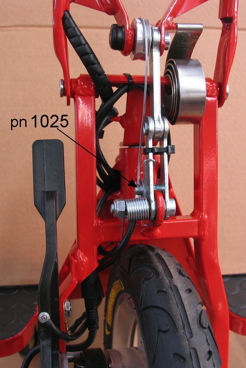
# Introduce the new cable from the rear end (pay attention to the junction
point of the two outer cable sections as shown in Pic
C3.5. While introducing the cable, apply some grease on it. Routing of the
cable on the front fork area is that shown in Pic
C3.6. In particular the cable is to go through the hole of the pin (pn
1025)
# Pic C3.4 - Introduce the front end of the
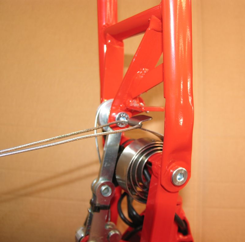
cable in the hole of the clamp (pn 3512) at the handlebar. The correct tension
of the steel cable is obtained by temporarily laying the end of the outer cable
over the edge of the washer A (Pic C3.7) and
then pulling the cable quite tight.
# Pic C3.4 - Tighten the screw of the clamp
(pn 3512);
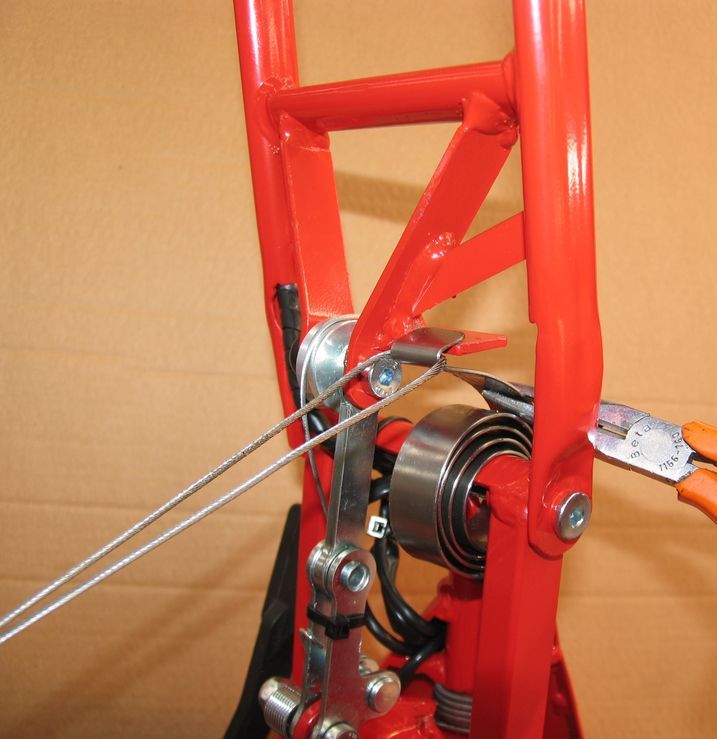
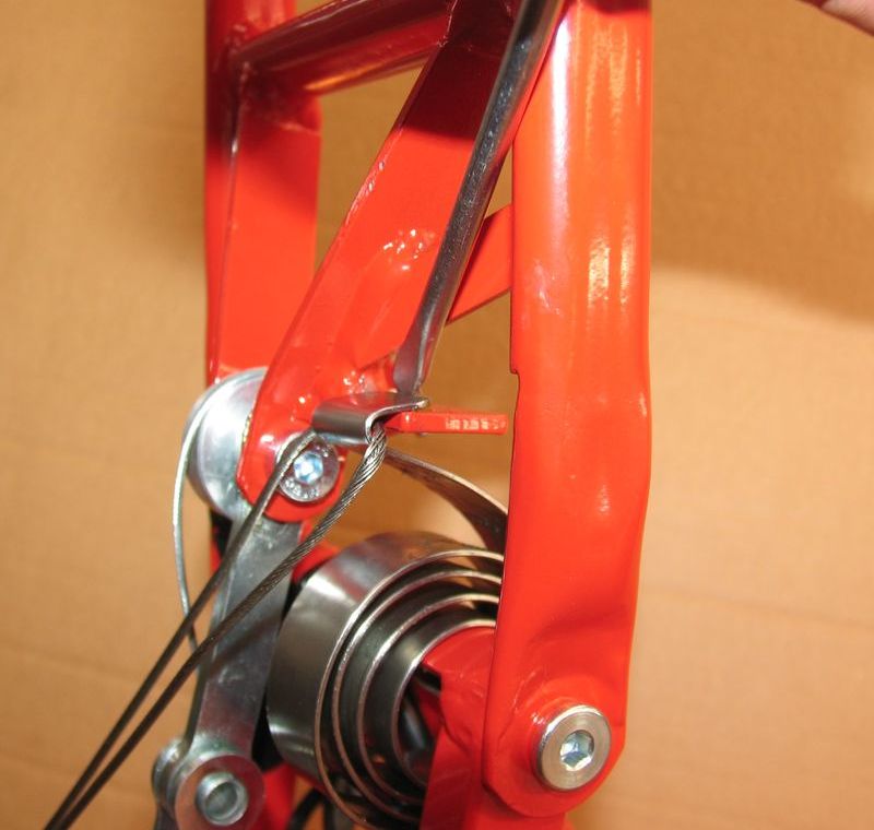
# Pic C3.7 - Remove the end of the outer
cable from the edge of the washer A
# Pic C3.4 - Cut the part of the steel cable
exceeding 5 mm from the clamp surface
# Pic C3.3 - Fit the cable cap (pn 489) at
the end of the cable and clamp it; fit the plastic cap (pn 474) on the screw of
clamp (pn 3512)
# Pic C3.5 - Press the folding red button
and check if while the scooter is folding the top of the handlebar hits against
the back rest. If it hits, unscrew a little bit the adjustment device (pn 3163)
until obtaining that the top of the handlebar does not hit against the back
rest when folding. After having unscrewed the adjustment device tighten the
corresponding nut acting as a lock nut.
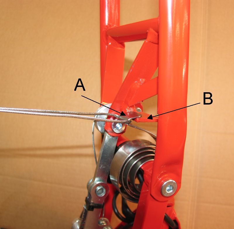
# When reassembling the RH side cover on the scooter pay attention to
that:
* the position of the light sensor and of the LED light fitted in the
scooter controller correspond to the two holes (A) and (B) in the cover (Pic C3.1)
* the wires of the electric loom are not pinched between the cover and the
frame.
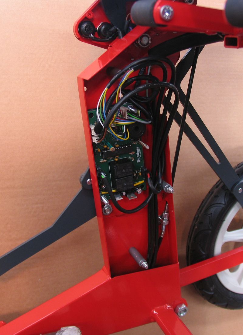
C.4) Scooter Controller replacement
# Pic C4.1 - Remove the 3 plastic caps on
the RH side cover; unscrew and remove the three nuts underneath
# Pic C4.2 - Remove the cover
# Disconnect the 8 connectors from the controller
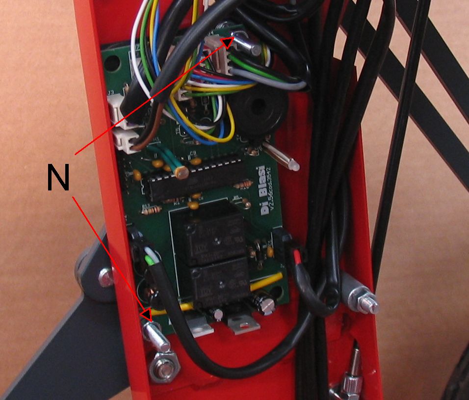
# Pic C4.3 - Unscrew and remove the 2 nuts
(N) using an 8 mm box wrench
# Remove the controller
# When reassembling the RH side cover on the scooter pay attention to
that:
* the position of the light sensor and of the LED light fitted in the scooter
controller correspond to the two holes (A) and (B) in the cover (Pic C4.1)
* the wires of the electric loom are not pinched between the cover and the
frame
* when connecting again the connectors on the scooter controller pay
attention to the connectors (J5) and (J7) can be distinguished only because the
two parts of J5 are red coloured (Pic C4.4)
C.5) Motor Controller replacement
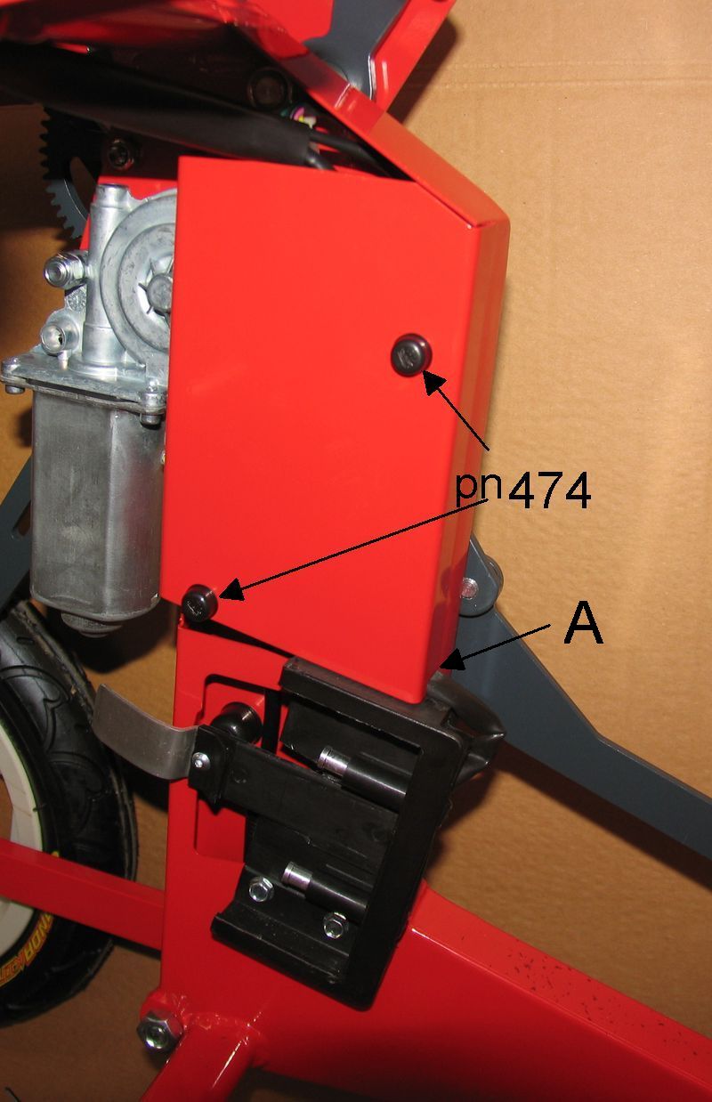
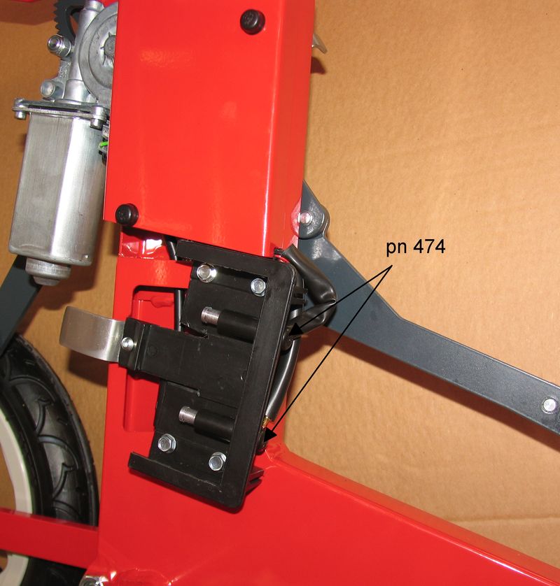
# Pic C5.1 - Remove the 2 plastic caps (pn
474) on the LH side cover; unscrew and remove the 2 nuts underneath
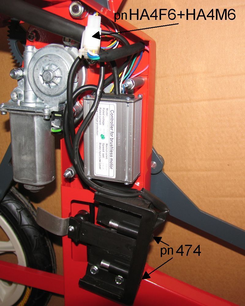
# Pic C5.2 - Remove the cover
# Pic C5.2 - Disconnect the two parts of
the 6 wires connector (pn HA4F6+HA4M6)
# Pic C5.2 - Remove the two plastic caps
(pn 474) at the end of the two contacts on the battery support
# Pic C5.3 - Unscrew the two nuts
underneath
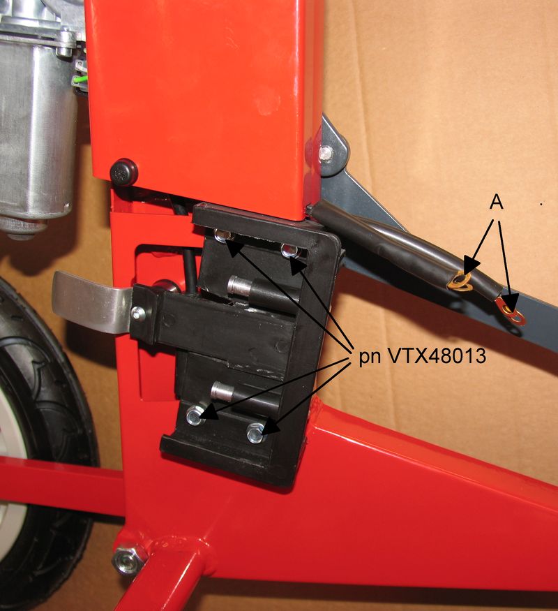
# Pic C5.4 - Disconnect the round
connectors from the battery support terminals and remove the plastic sheaths
(A) covering the end of the relevant wires
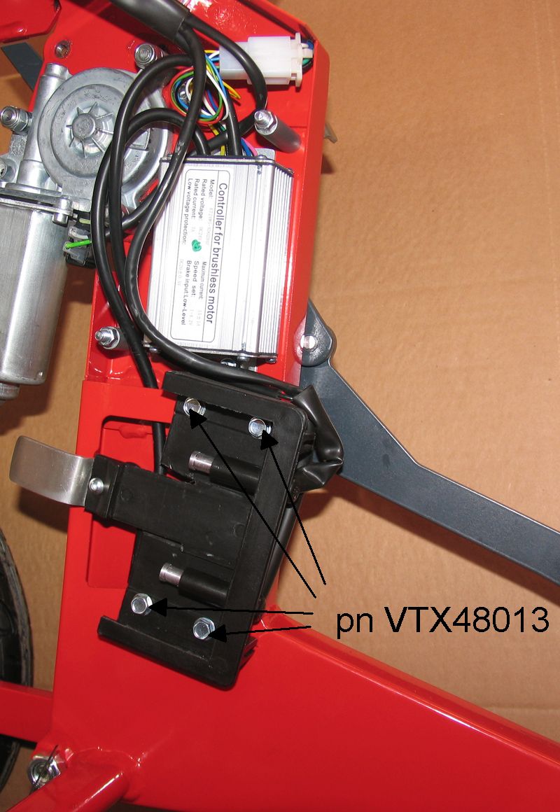
# Pic C5.4 - Unscrew the 4 screws (pn
VTX48013) holding the battery support
# Remove the battery support
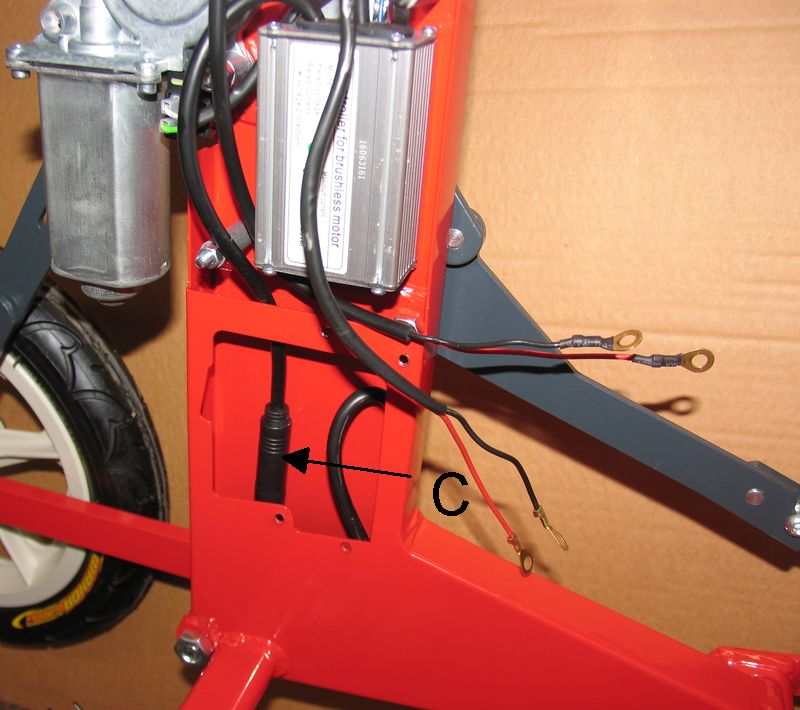
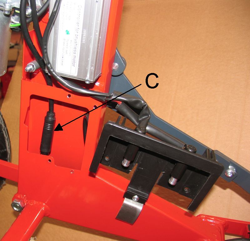
# Pic C5.5 - Disconnect the two parts of
the round connector (C). To avoid damage to the connector do not disconnect
them by pulling the relevant cables but by pulling the two parts.
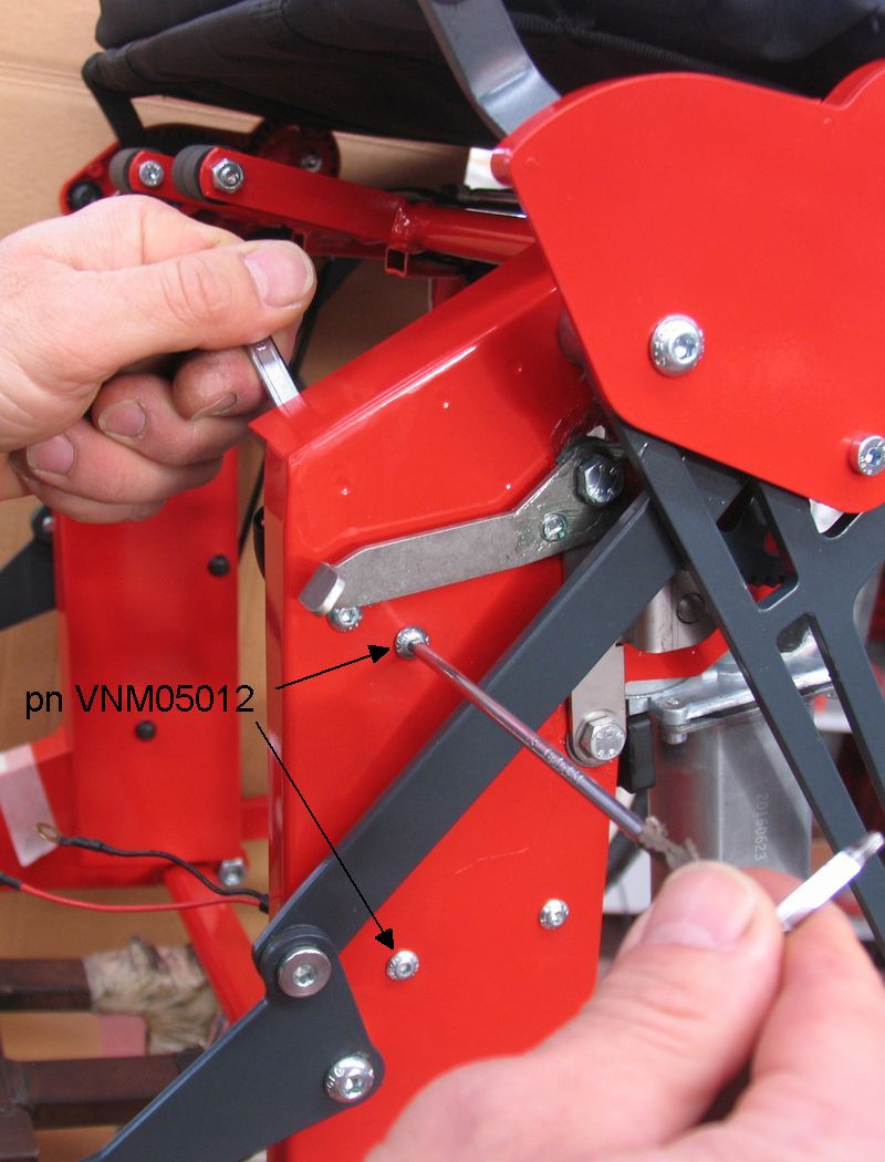
# Pic C5.6 - Unscrew the two screws (pn
VNM05012) which hold the controller to the frame
# When reassembling pay attention to:
* when connecting the two parts of the round connector, the two arrows
marked on each of the two parts have to correspond each other;
* when connecting the two parts of the square connector (pn HA4F6+HA4M6)
they have to remain engaged each other by the small plastic hook
* to not pinch the wires between the cover and the frame, especially in
the point (A) of (Pic C5.1)
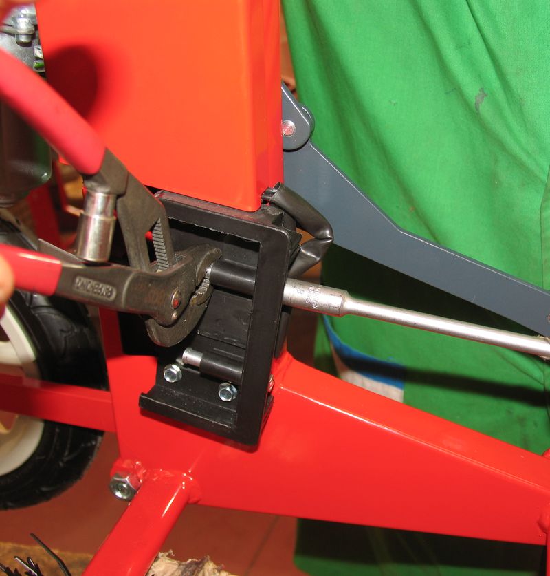
C.6) Battery support replacement
# Pic C6.1 - Remove the two plastic caps
(pn 474) at the end of the two contacts on the battery support and ...
# Pic C6.2 - … unscrew the two nuts
underneath
# Pic C6.3 - Disconnect the round
connectors (A) from the battery support terminals
# Pic C6.3 - Unscrew the 4 screws (pn
VTX48013) holding the battery support
# Remove the battery support
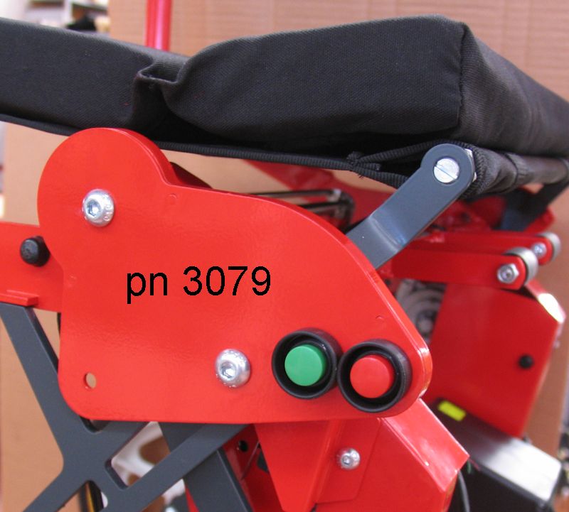
C.7) Folding-unfolding stop switches adjustments
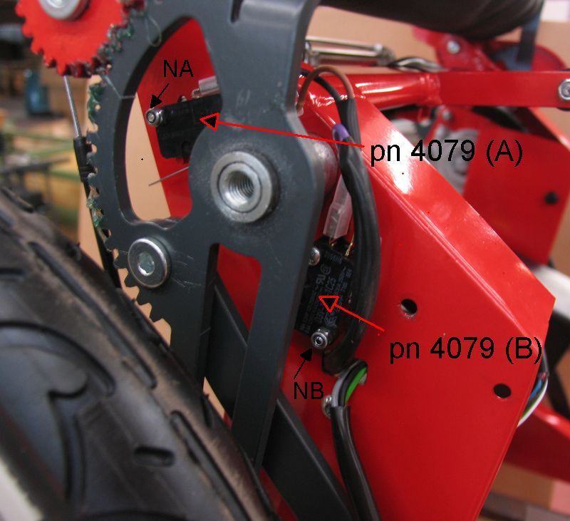
# Notice
The two stop switches (pn 4079) are hidden by the cover (pn 3079) (Pic C7.1). For a better visibility Pic C7.2 shows the two switches after that the
cover (pn 3079) has been removed: however for the purposes of this section it
is not necessary to remove this cover.
The functions of the two switches are:
* the switch (A) stops the unfolding of the scooter
* the switch (B) stops the folding of the scooter.
# Pic C7.3 - Remove the 3 plastic caps (pn
474) on the RH side cover and the three nuts underneath
# Pic C7.4 - Remove the cover
# Pic C7.5 - To delay unfolding stop
* Loosen the screw of the switch (A), i.e. the screw corresponding to nut
(NA) in Pic C7.2
* move the switch a little bit upwards
* tighten again the screw
# Pic C7.5 - To anticipate unfolding stop
* Loosen the screw of the switch (A), i.e. the screw corresponding to nut
(NA) in Pic C7.2
* move the switch a little bit downwards
* tighten again the screw
# Pic C7.6 - To delay folding stop
* Loosen the screw of the switch (B), i.e. the screw corresponding to nut
(NB) in Pic C7.2
* move the switch a little bit forward
* tighten again the screw
# Pic C7.6 - To anticipate folding stop
* Loosen the screw of the switch (B), i.e. the screw corresponding to nut
(NB) in Pic C7.2
* move the switch a little bit rearward
* tighten again the screw
# When reassembling the RH side cover on the scooter pay attention to
that:
* the position of the LED light and the light sensor fitted in the scooter
controller correspond to the two holes (A) and (B) in the cover (Pic C7.3)
* the wires of the electric loom are not pinched between the cover and the
frame
C.8) Folding/unfolding buttons replacement
# Pic C8.1 - Remove the 3 plastic caps (pn
474) on the RH side cover and the three nuts underneath
# Pic C8.2 - Remove the cover
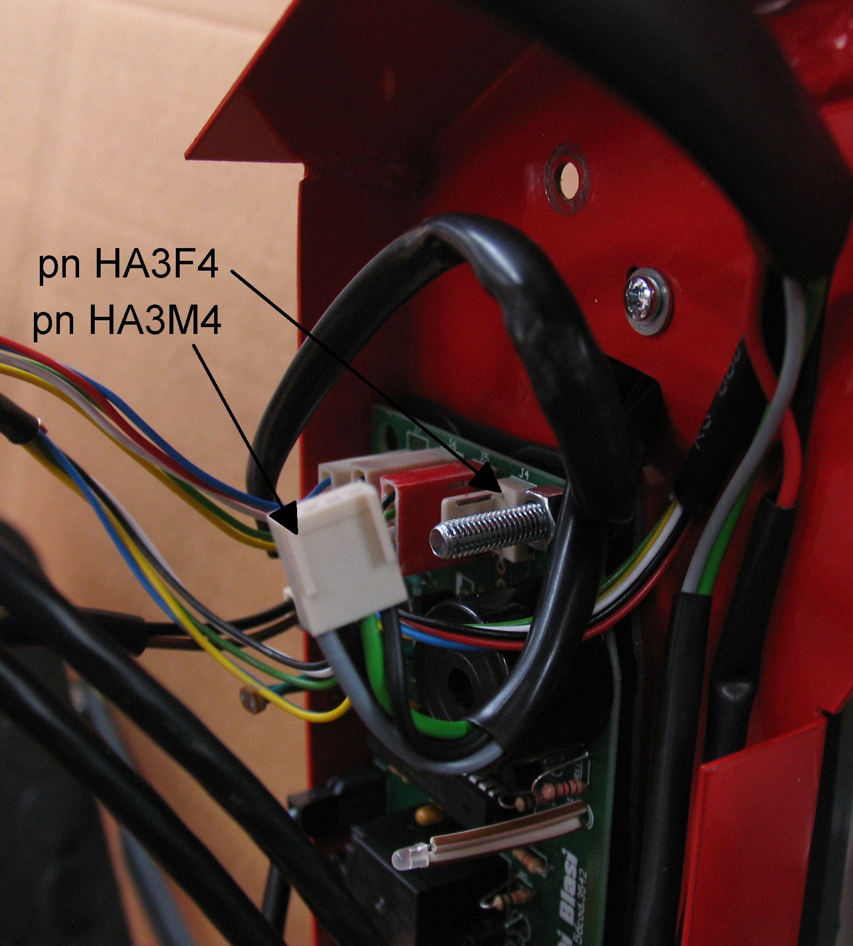
# Pic C8.3 - Disconnect connector (pn
HA3M4) from the corresponding connector pn (HA3F4) (the position of this
connector is marked J4 on the card)
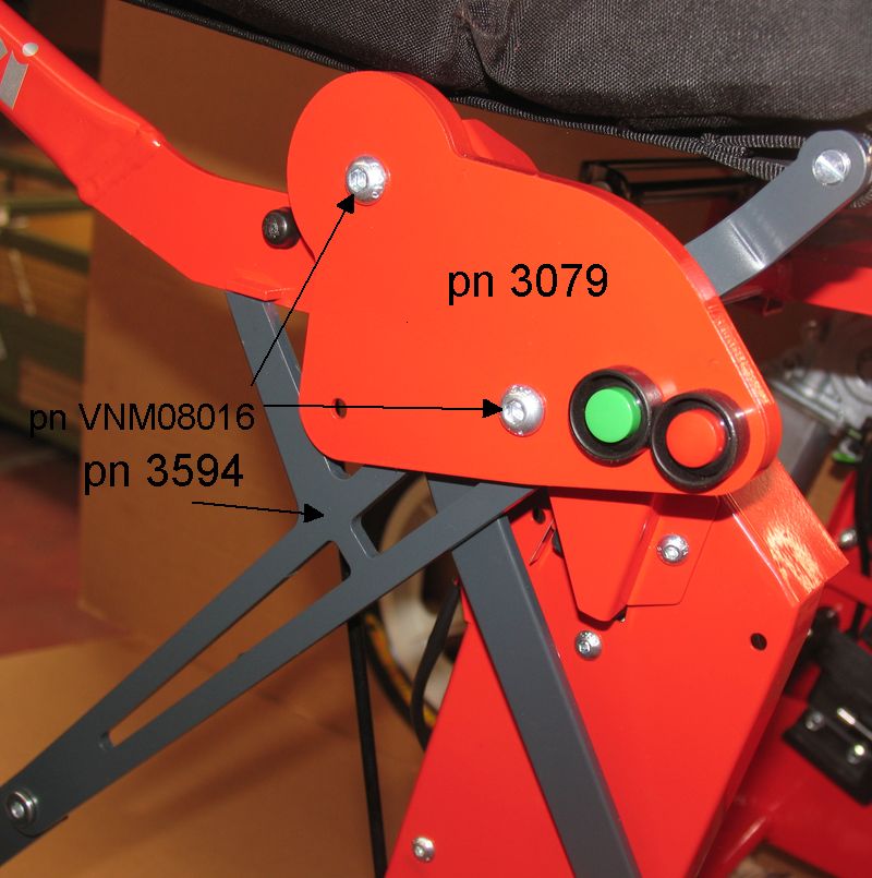
# Pic C8.4 - Unscrew screw (pn VNM05045)
and remove the cover (pn 3541)
# Pic C8.5 - Unscrew the two screws (pn
VNM08016) and remove the cover assembly (pn 3079)
# When reassembling the cover assembly on the scooter:
* add some drops of thread lock liquid in the treads of screws (pn
VNM08016)
# When reassembling the RH side cover on the scooter pay attention to
that:
* the position of the LED light and the light sensor fitted in the scooter
controller correspond to the two holes (A) and (B) in the cover (Pic C8.1)
* the wires of the electric loom are not pinched between the cover and the
frame.
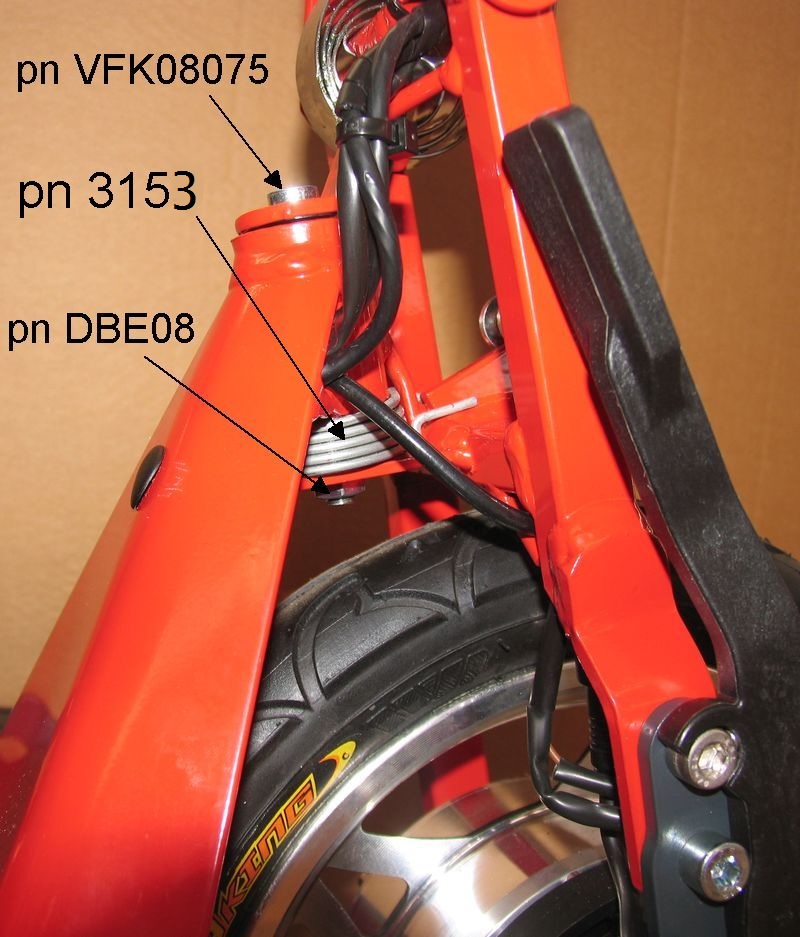
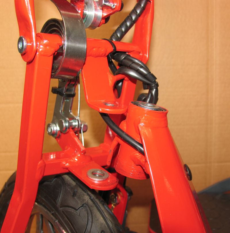
C.9) Front fork returning spring replacement
# Pic C9.1 - Unscrew and remove the lock
nut (pn DBE08) and the screw (pn VFK08075)
# Pic C9.2 - Move forward the front fork
assembly and remove the spring (pn 3153)
# Fit the new spring according the steps shown in the following pictures:
* Pic C9.3
* Pic C9.4
* Pic C9.5
* Pic C9.6
# Pic C9.6 + Pic
C9.7 - Fit the two washers (pn MAX10) centred on the spacer protruding from
the steering tube bearings. The bottom washer can be kept on the spacer using a
little bit grease as glue
# Pic C9.8 - Reassemble the front fork on
the steering tube. The front fork has to be introduced in the steering tube
while in straight position so that the protrusion (A) on the fork fits at the
centre of the two ends (B) of the spring
# Pic C9.1 - Screw the screw (pn VFK08075)
on the lower plate of the fork. Screw the lock nut (pn DBE08) after having
added some drops of lock liquid in its threads
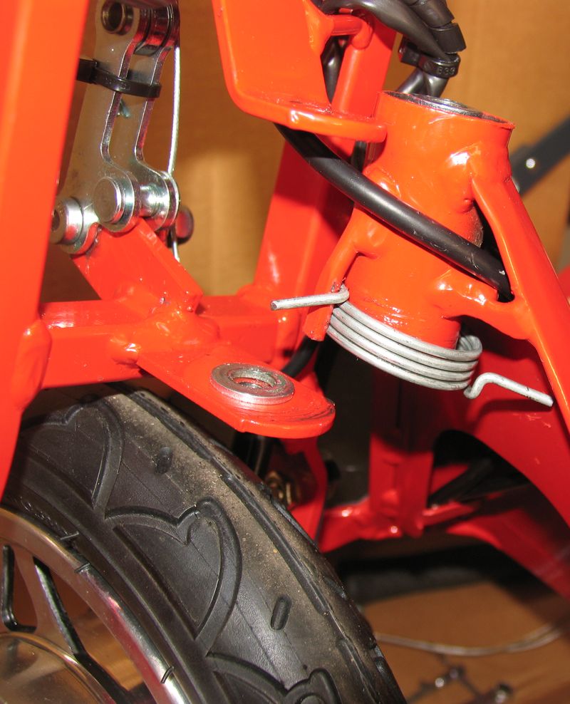
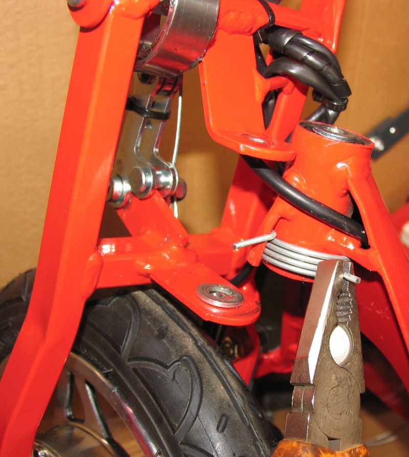
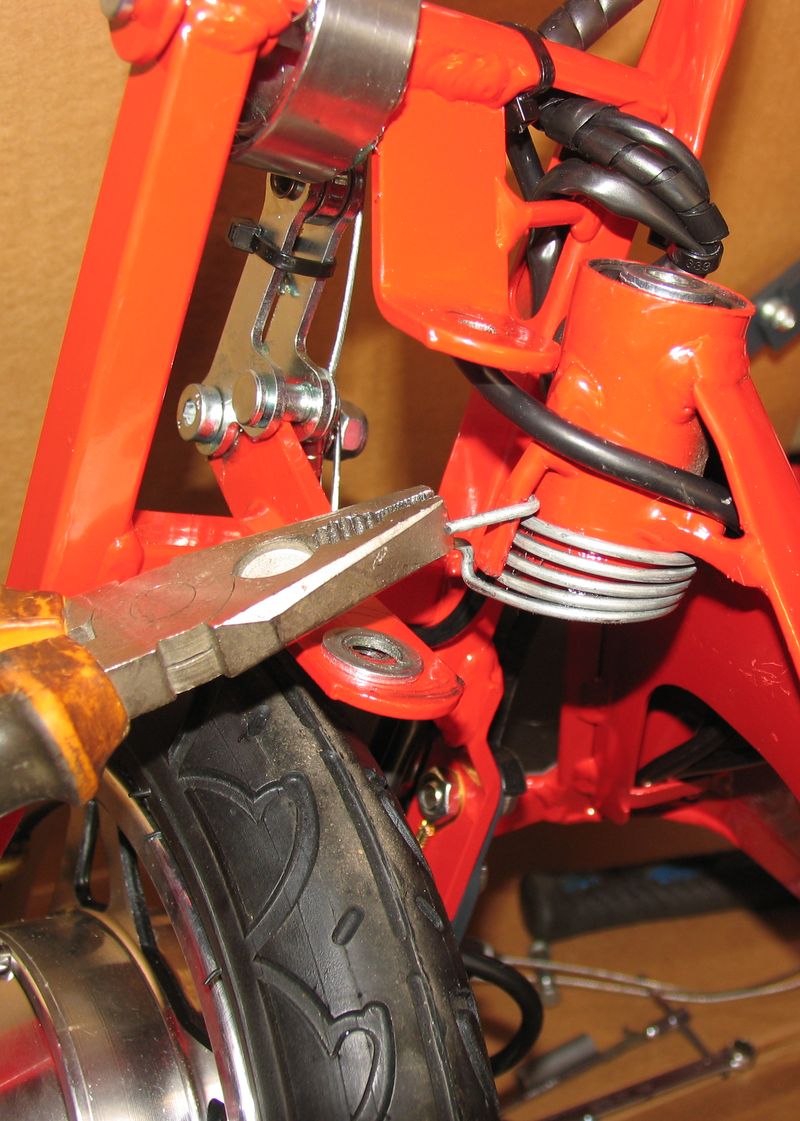
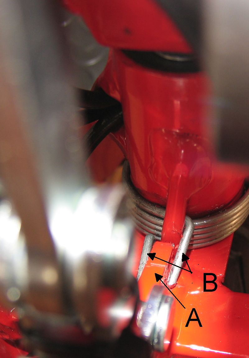
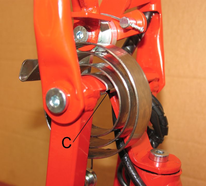
# Pic C9.10 - Check that the tip of the LH
end of the spring is positioned in the bottom corner (C) of the protrusion (A)
(Pic C9.9). If not, bend the spring end using a
pliers
# Fold the scooter and check if, while folding, the handlebar remains
centred as regards to the back rest. If it turns toward right or left side,
bend a little bit the suitable end of the spring: if the handlebar turns toward
the RH side, bend the RH tip of the spring towards the LH side; if the
handlebar turns toward the LH side, bend the LH tip of the spring towards the
RH side (In this case RH side or LH it that when looking the front of the
scooter)
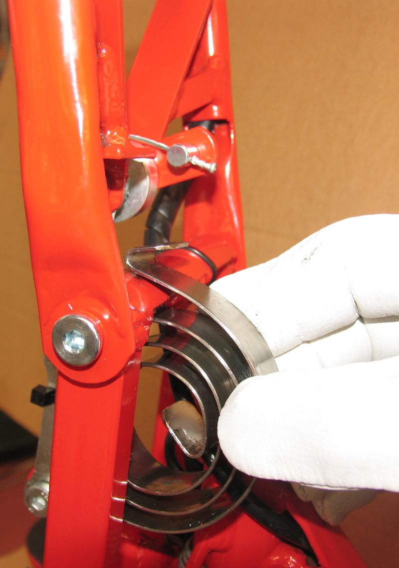
C.10) Handlebar returning spring replacement
(For safety reasons the operations here described
should be carried out while wearing suitable gloves)
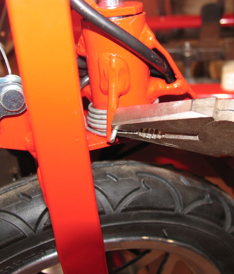
# Pic C10.1 - Seize the spring with a
pliers
# Pic C10.2 - Bend forward the spring so
to …
# Pic C10.3 - … so to remove its bended
end (A) from the handlebar retainer (B)
# Pic C10.4 - Turn the spring round the
front fork bar until removing it.
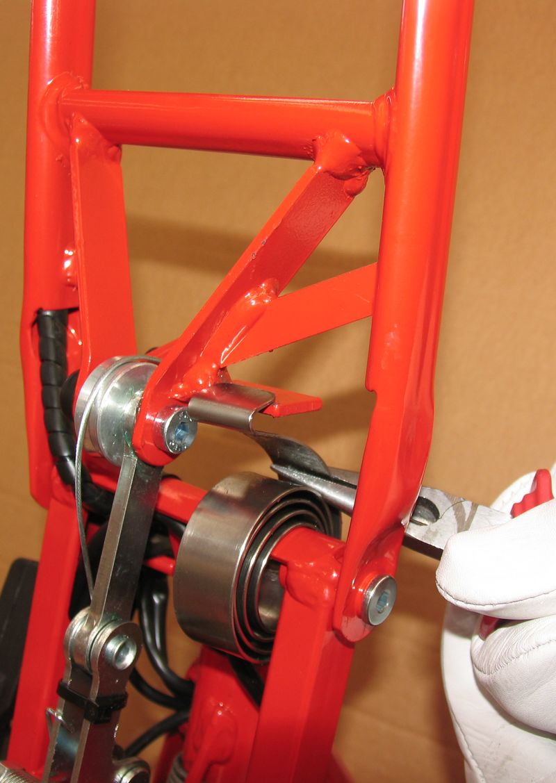
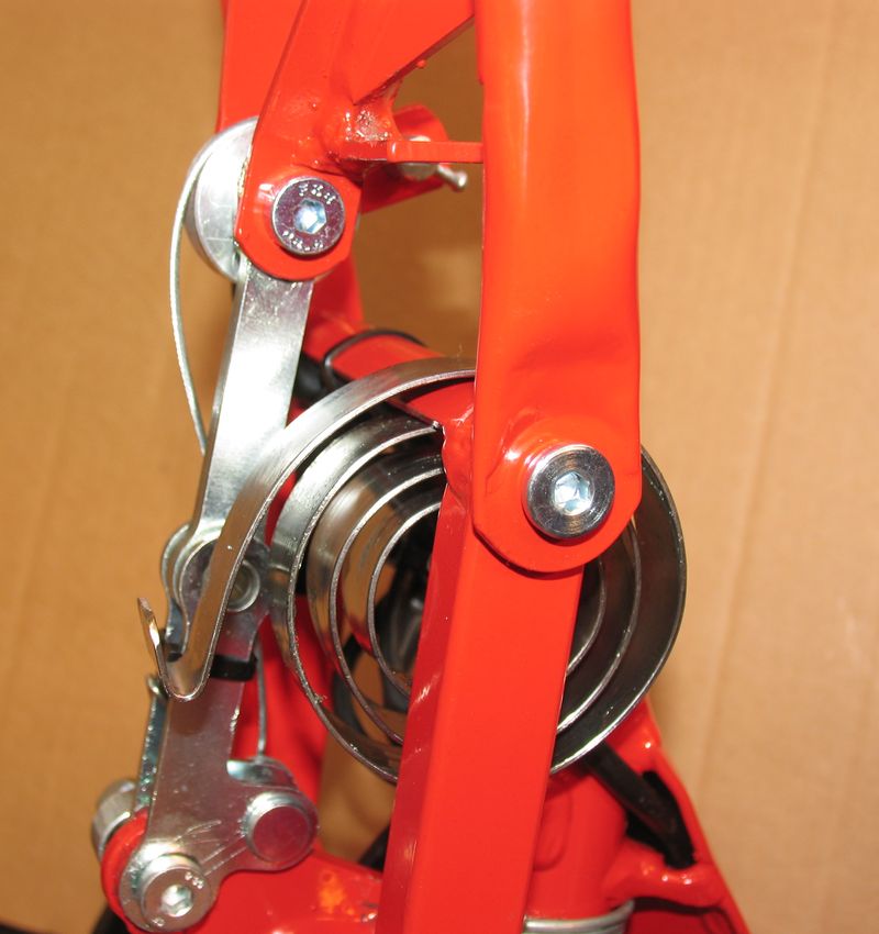
# Pic C10.5 - Put the beginning of the
spiral of the new spring in the front fork bar
# Pic C10.6 - “Screw” the spring round the
front fork bar until ...
# Pic C10.7 - … until the internal bent
end (C) of the spring is hooked by the front fork bar. Add a little bit grease
inside the spiral of the spring.
# Pic C10.8 - Hang the external bent end
of the spring to a steel cable (like that used for the brakes).
# Pic C10.9 - Pull the steel cable
backwards so to turn the spring of about 180°
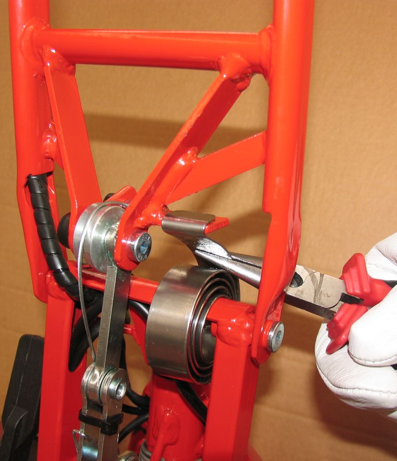
# Pic C10.10 - Keep the spring in this
position by seizing it with a pliers and meantime move the cable frontwards
# Pic C10.11 - Pull the steel cable so to
turn the spring for further about 180° until …..
# Pic C10.12 - … until the bended end (A)
of the spring can be hanged to the handlebar retainer (B)
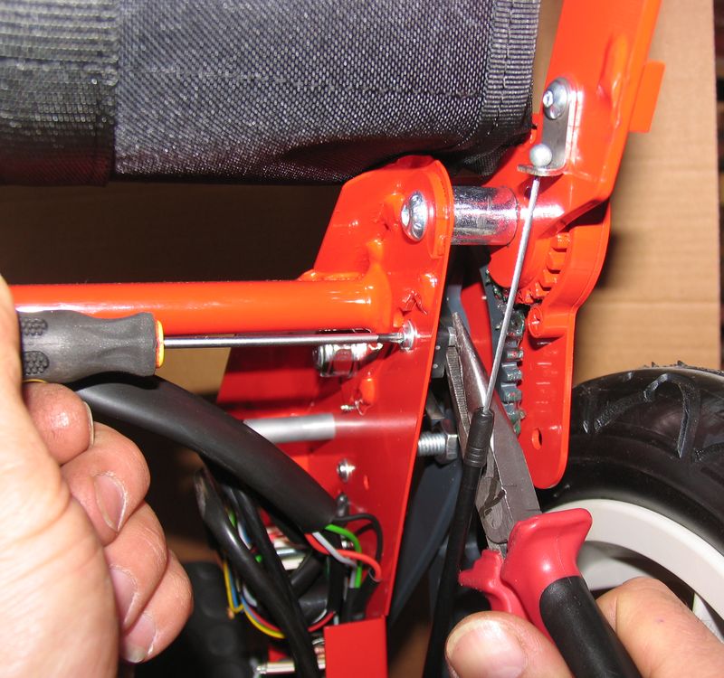
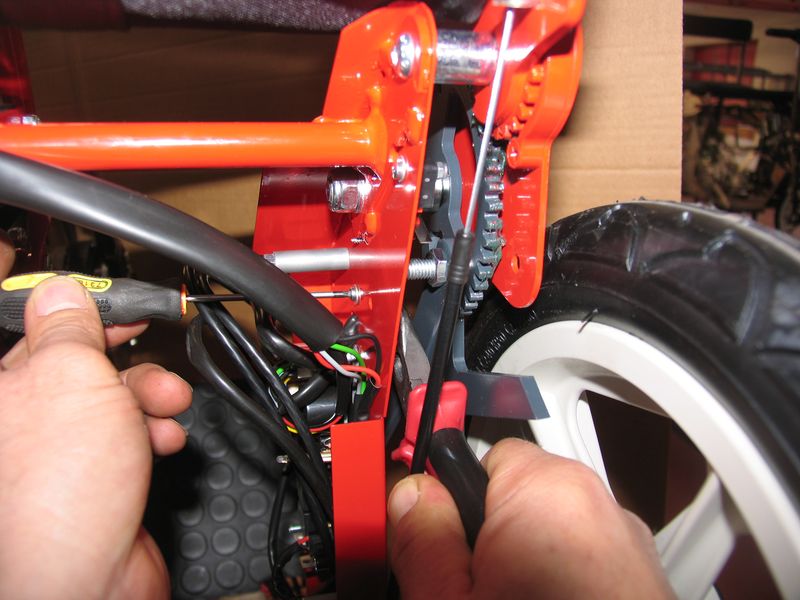
# To release the steel cable if it remains embedded between the spring and
the retainer:
* or use a pliers (Pic C10.13)
* or use a screwdriver (Pic C10.14)
C.11) RH loom (pn 3135) and LH loom (pn 3149) replacement
# Notices
* RH loom (pn 3135) and LH loom (pn 3149) must be disassembled in the same
operation.
* when pulling the looms as here below described, use caution to avoid
damaging to the connectors fitted at their ends.
# Pic C11.1 - Remove the 3 plastic caps
(pn 474) on the RH side cover and the three nuts underneath
# Pic C11.2 - Remove the cover
# Pic C11.3 - Disconnect (J8) – (J7) -
(J5) connectors (see also wiring
diagram)
# Pic C11.4 - Pull the loom corresponding
to the connector (J8) at the RH hinge between footboard and main frame.
# From the same location pull the loom corresponding to connector (J7)
# From the same location pull the loom corresponding to connector (J5)
# Pic C11.5 - Bend a little bit the
retainer (A) below the RH side of the mounting of the footboard in order to
allow removing of the looms.
# From the location shown in Pic 11.5 pull the loom corresponding to
connector (J8) and then the looms corresponding to connectors (J7) and (J5)
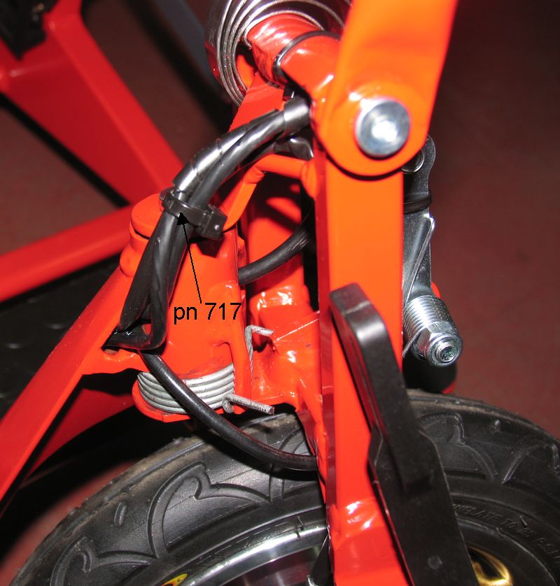
# Pic C11.6 - Cut the plastic clamp (pn
717)
# From this location pull the loom corresponding to connector (J8) and
then the looms corresponding to connectors (J7) and (J5)
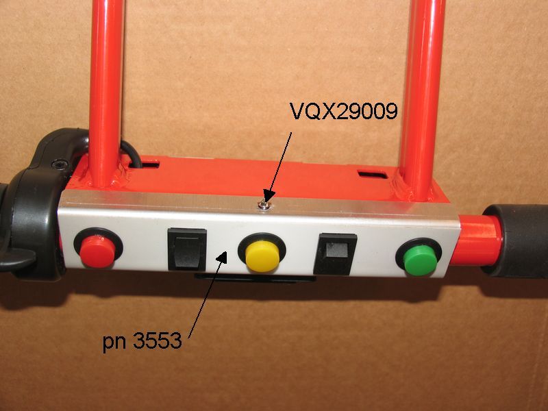
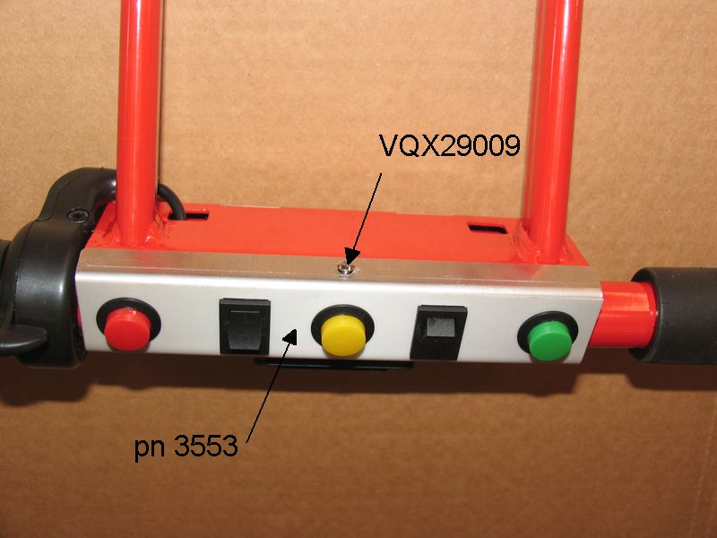
# Pic C11.7 - Unscrew the screw (pn
VQX29009) holding the control board assembly (pn 3553) and remove it from the
top of the handlebar (Pic C11.8)
# Pic C11.8 - Disconnect all the
connectors at the control board assembly (pn 3553)
# From the top of the handlebar pull at same time the two looms
corresponding to connector (J7) and (J5), i.e. respectively the LH loom (pn
3135) and the RH loom (pn 3149). While pulling from the top of the handlebar,
push the two looms upwards at the bottom of the handlebar (Pic C11.9). Before entering the connectors of the
two looms in the handlebar stem, put them one after the other as shown in Pic C11.10
# When reassembling:
* the two looms are to be entered in the same time in the different parts
of the frame, starting from the upper end of the handlebar, always keeping the
two connectors one behind the other as shown in Pic
C11.10
* when connecting again the connectors on the scooter controller pay
attention to the connectors (J7) and (J5) can be distinguished only because J5
is red coloured (Pic C11.3)
* bend to the original position the retainer (A) below the RH side of the
mounting of the footboard (Pic C11.5)
* pay attention to that the position of the LED light and the light sensor
fitted in the scooter controller correspond to the two holes (A) and (B) in the
cover (Pic C8.1)
* pay attention to that the wires of the electric loom are not pinched
between the cover and the frame.
C.12) Motor-controller loom (pn 3098) replacement
# Pic C12.1 - Remove the 2 plastic caps
(pn 474) on the LH side cover; unscrew and remove the 2 nuts underneath
# Pic C12.2 - Remove the cover
# Pic C12.2 - Unscrew the 4 screws (pn
VTX48013) holding the battery support
# Pic C12.3 - Remove the battery support
without disconnecting the cables
# Pic C12.3 - Disconnect the two parts of
the round connector (C). To avoid damage to the connector do not disconnect them
by pulling the relevant cables but by pulling the two parts.
# Pic C12.4 - Pull the loom at the LH
hinge between footboard and main frame
# Pic C12.5 - Bend a little bit the
retainer (A) below the LH side of the mounting of the footboard in order to
allow removing of the loom.
# Pic C12.6 - Cut the plastic clamp (A)
(pn 717)
# Pic C12.6 - Pull the loom in the
direction (C) in order to remove it from the footboard mounting.
# Pic C12.6 - Disconnect the two parts of
the round connector (B) ( To avoid damage to the connector do not disconnect
them by pulling the relevant cables but by pulling the two parts.
# Pic C12.6 - Pull the loom in the
direction (D) in order to remove it from the front fork
# When reassembling:
* Pic C12.5 - Bend to the original position
the retainer (A) below the LH side of the mounting of the footboard.
* When connecting the two parts of the round connector at the motor end
and at the motor controller end, pay attention to that the arrow marked on each
of the two parts corresponds to that on the other part.
* Pay attention to not pinch the wires between the cover and the frame,
especially in the point (A) of (Pic C12.1)
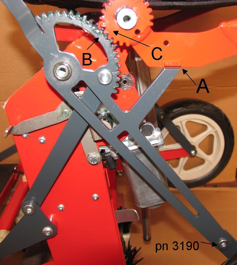
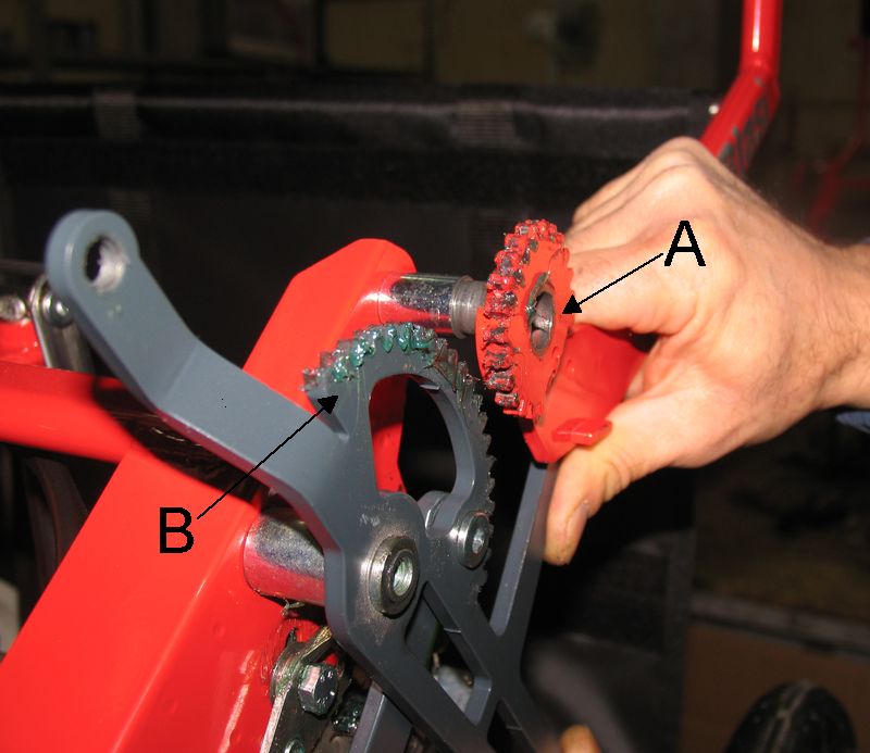
C.13) Gears assembly (pn 3582+pn3583) replacement (Pic C13.2)
# Pic C13.1
– Disconnect the folding automatic mechanism by pushing the lever (A) upwards
and then fold manually the scooter (see owner's manual – Sec. 3 – Last par.)
# Pic C13.2
- Unscrew nut (pn DIX06) and screw (pn VFX06050)
# Pic C13.2
- Remove gears assembly (pn 3582+pn3583) paying attention to not lose the
bushing (pn 3600) inside the gear (pn 3582)
# When reassembling
* add a little bit grease in the teeth and inside the said bushing
* Connect again the folding automatic mechanism by pushing the lever (A)
downwards (see owner's manual – Sec. 3 – Last par.)
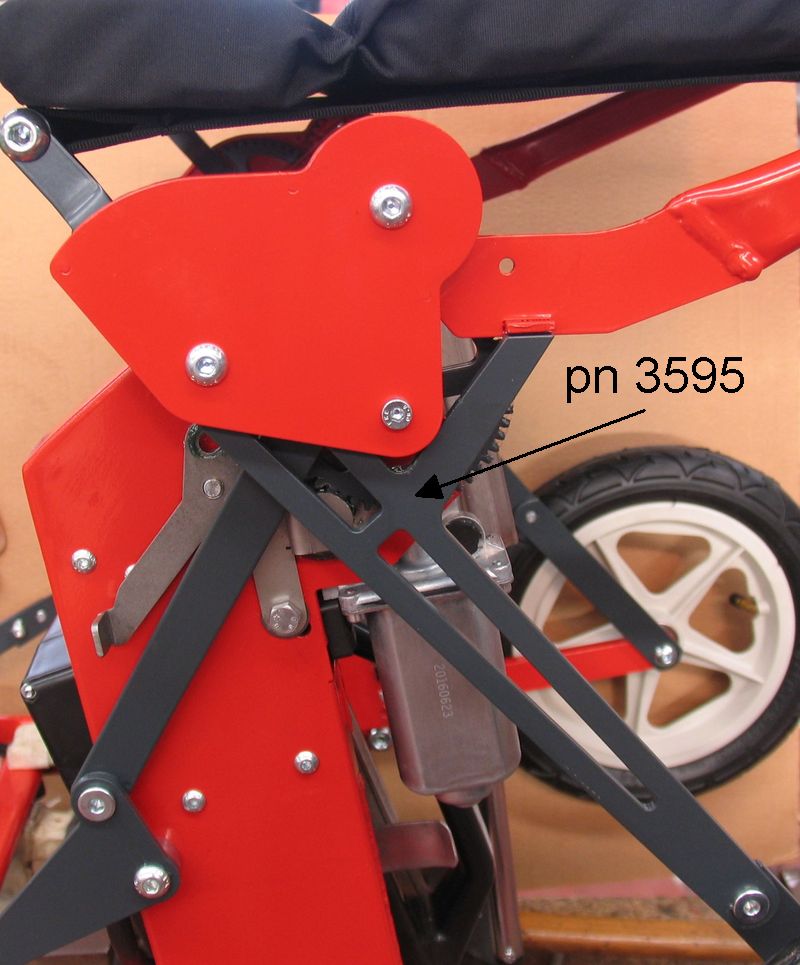
C.14) Geared rod (LH side) (pn 3595) (Pic C14.1) replacement
# Remove the gears assembly (pn 3582+pn3583) (see Sec C.13)
# Unfold completely the scooter manually
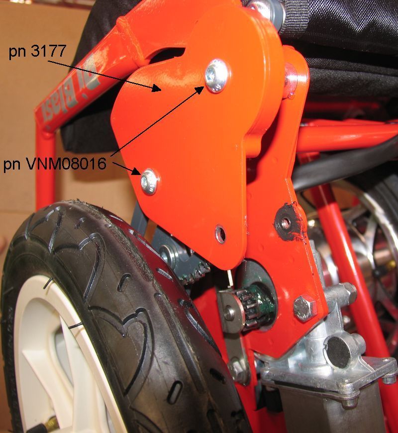
# Pic C14.3
- Unscrew the screws (pn VNM08016) and remove the cover (pn 3177) (Pic C14.2) paying attention to not lose the two
washers (A)
# Pic C14.4
- Measure the gap (A) between the seat frame protrusion and the geared rod
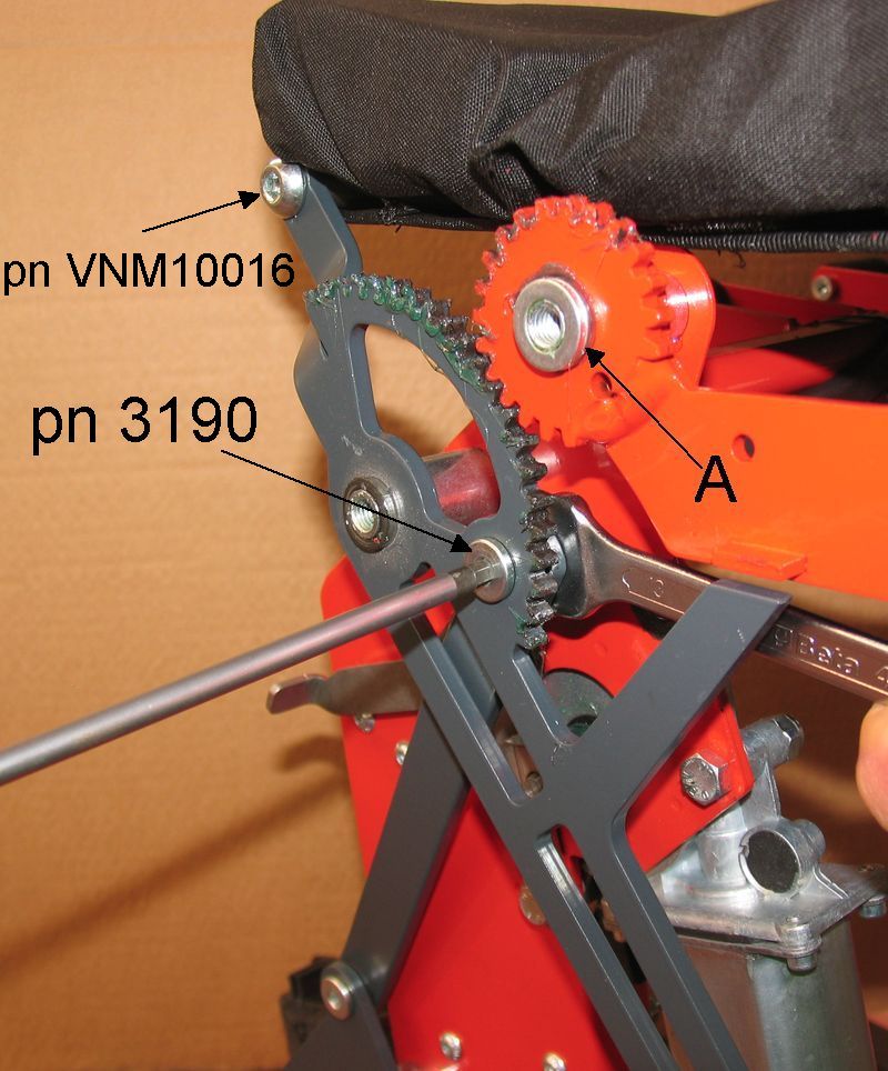
# Pic C14.3 -
Unscrew the upper screw (pn 3190) paying attention to not lose the washer
underneath
# Pic C14.4
- Unscrew the lower screw (pn 3190) paying attention to not lose the shim
underneath
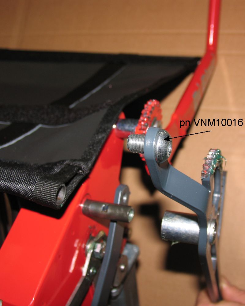
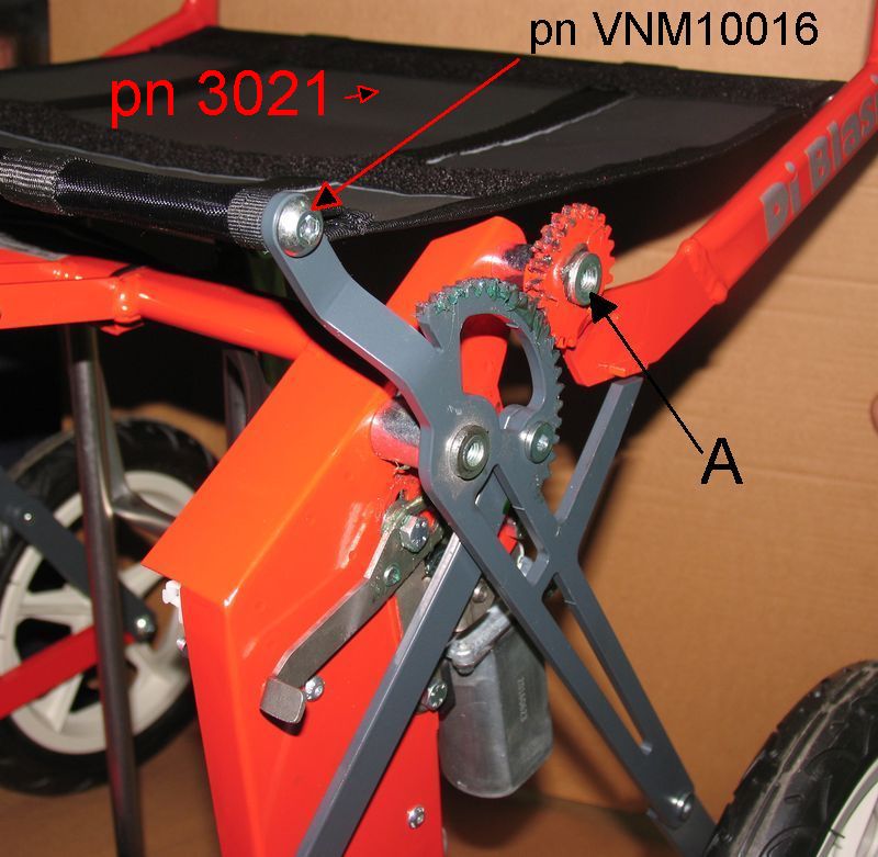
# Pic C14.6
- While removing the geared rod (LH side) (pn 3595) the screw (pn VNM10016)
comes out from the seat front bar.
# Pic C14.6
- Unscrew and remove the screw (pn VNM10016)
# When reassembling:
* Pic C14.4
- Mesh the teeth (B) and (C) so that the gap (A) is the same than that measured
before disassembling
* Add some grease on the teeth
* Add some drops of thread lock liquid in the threads of all the screws
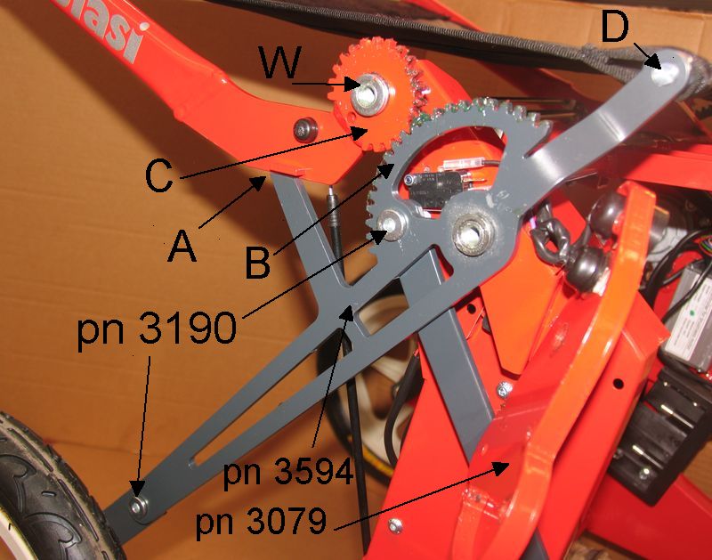
C.15) Geared rod (RH side) (pn 3594) (Pic C15.1) replacement
# Unfold completely the scooter
# Pic C15.1
- Unscrew the two screws (pn VNM08016)
# Pic C15.2
- Move sideways the cover assembly (pn 3079) paying attention to not lose the
two washers (W)
# Pic C15.2
- Measure the gap (A) between the seat frame protrusion and the geared rod
# Pic C15.2 -
Unscrew the upper screw (pn 3190) paying attention to not lose the washer
underneath
# Pic C15.2
- Unscrew the lower screw (pn 3190) paying attention to not lose the shim
underneath
# Pic C15.2
- While removing the geared rod (RH side) (pn 3594) the screw (D) comes out
from the seat front bar.
# Pic C15.2
- Unscrew and remove the the screw (D).
# When reassembling:
* Pic C15.2
- Mesh the teeth (B) and (C) so that the gap (A) is the same than that measured
before disassembling.
* Add some grease on the teeth
* Add some drops of thread lock liquid in the threads of all the screws
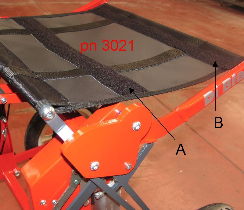
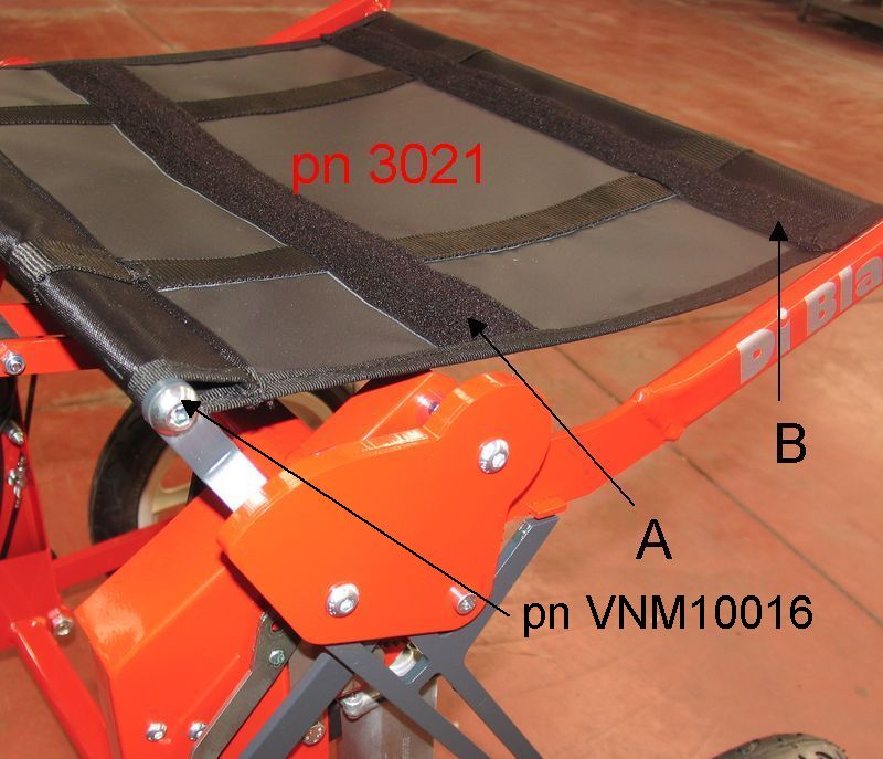
C.16) Seat sheet (pn 3021) replacement (Pic C16.1) (Versions until 31-12-2016)
# Sec C.13 - Fold completely the scooter and disassemble the gears
assembly (pn 3582+pn 3583)
# Pic C16.3 - Unscrew the screws (pn
VNM08016) and remove the cover (pn 3177) (Pic C16.2)
paying attention to not lose the two washers (A)
# Unfold completely the scooter
# Pic C16.3 - Remove the seat cushion.
# Pic C16.4 - Measure the gap (A) between
the seat frame protrusion and the geared rod
# Pic C16.3 - Unscrew and remove the screw
(pn VNM10016)
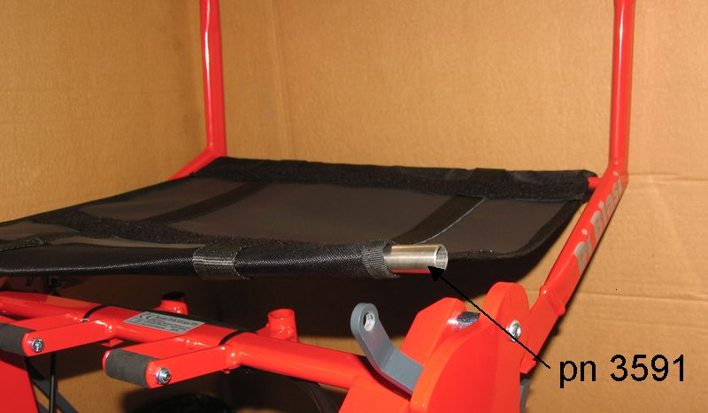
# Pic C16.5 - Remove the seat front bar
(pn 3591) from the front edge of the seat sheet
# Pic C16.6 - Turn backwards the seat
sheet so to make it hanging to seat rear bar.
# Pic C16.7 - Disconnect the seat frame gear
(A) from the geared rod (LH side) (B) by bending sideways the bottom arm of the
seat frame.
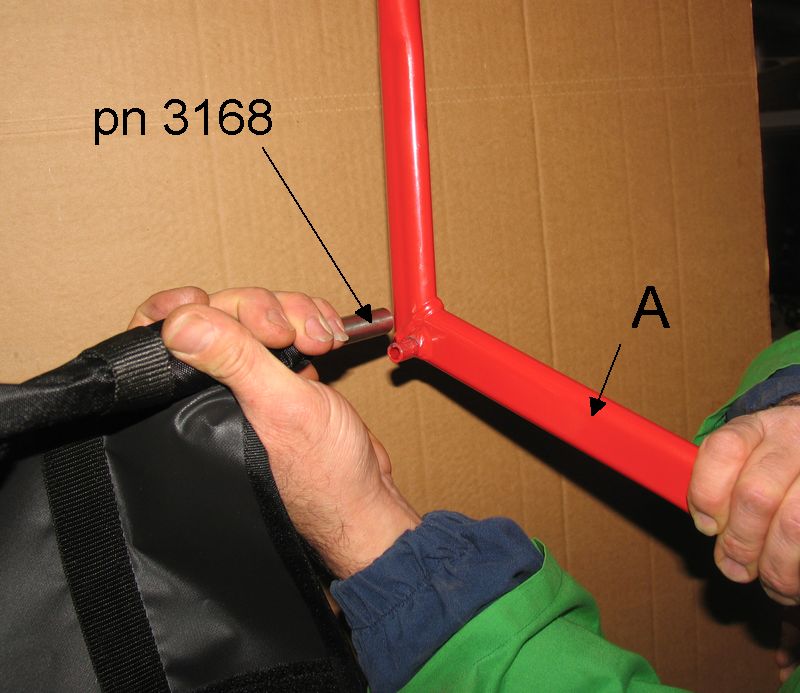
# Pic C16.8 - Bend sideways the bottom arm
of the seat frame (A) in order to disconnect it from the end of the seat rear
bar (pn 3168)
# Remove the seat sheet from the seat rear bar.
# When reassembling pay attention to:.
* Pic C16.4 - Mesh the teeth (B) and (C)
so that the gap (A) is the same than that measured before disassembling.
* The seat sheet is to be fitted so that two adhesive strips (A) and (B)
are in the position shown in Pic C16.1
* Add some grease on the teeth
* Add some drops of thread lock liquid in the threads of all the screws
C.17) Seat sheet (pn 3021) replacement (Versions
from 01-01-2017)
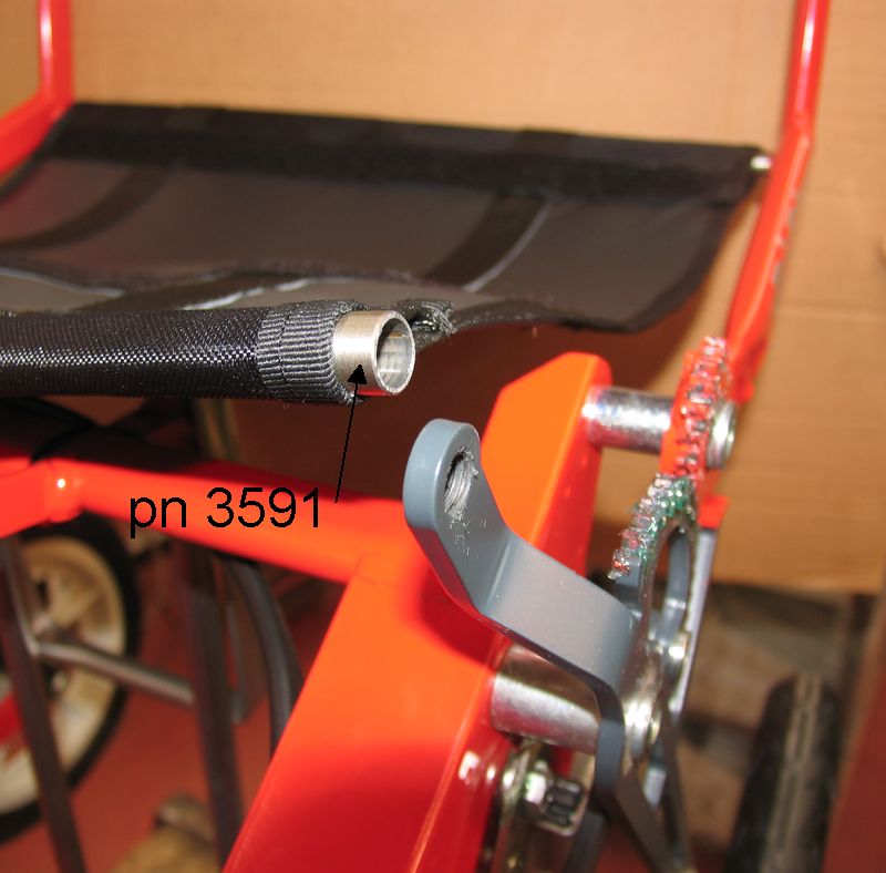
# Pic C17.1 - Remove the seat cushion .
# Pic C17.1 - Unscrew and remove the screw
(pn VNM10016)
# Pic C17.2 - Remove the seat front bar
(pn 3591) from the front edge of the seat sheet
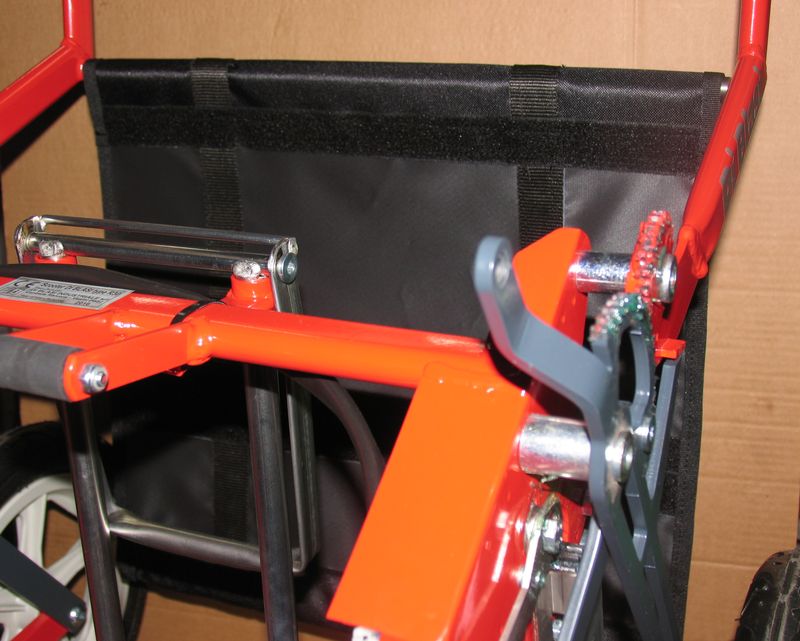
# Pic C17.3 - Turn backwards the seat
sheet so to make it hanging to seat rear bar
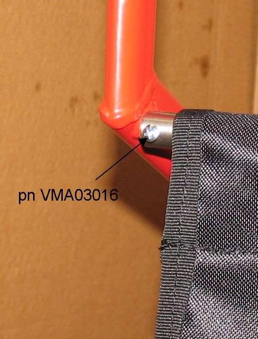
# Pic C17.4 – Unscrew the screw (pn
VMA03016) at the LH from the rear seat bar. This screw is screwed on a nut on
the opposite side on the bar.
# Pic C17.5 – Move the LH end of the seat
rear bar (pn 3166) rearward in order to disconnect from seat frame protrusion
(A) and then remove the bar from the seat sheet.
# Replace the sheet
# When reassembling pay attention to:.
* The seat sheet is to be fitted so that two adhesive strips (A) and (B)
are in the position shown in Pic C17.1
C.18) Cancelling the reverse speed sound (beep) warning
(For safety reasons cancel the reverse speed sound
warning only when absolutely necessary)
# Turn rearward the rocker device for setting reverse speed of the
scooter.
# Press the horn green button and immediately after also the main switch
yellow button. Two short beep advise that the reverse speed warning has been
cancelled.
# To reintroduce the reverse speed warning follow the same steps as above.
Three short beep advise that the reverse speed warning has been reintroduced.