INSTALLATION AND USE
for
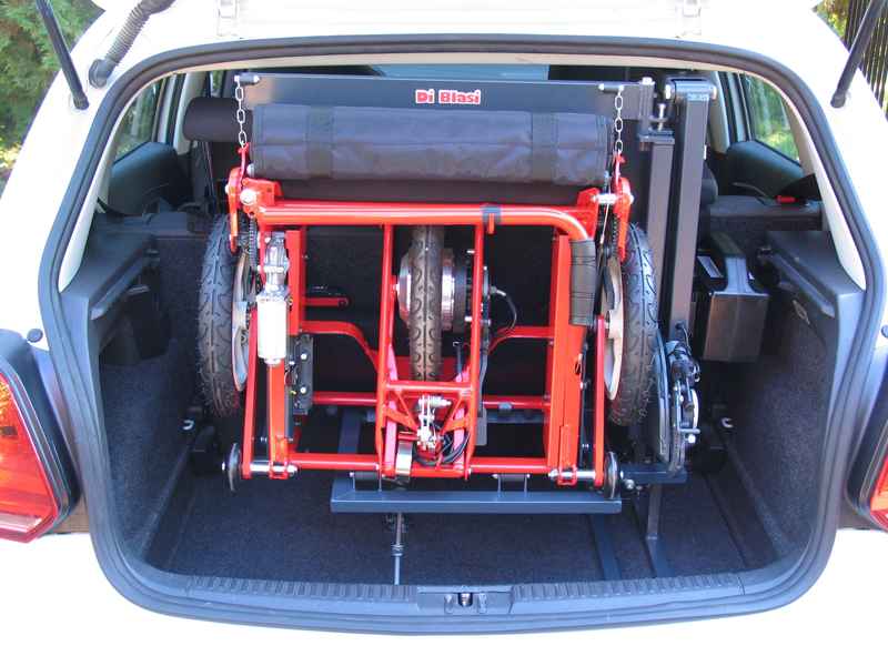
DI BLASI mobility scooter mod. R30
SAFETY WARNINGS
The lifter is designed for loading and unloading from the car boot only the DI BLASI mobility scooter mod. R30. It must not be used for loading and unloading other items.
Do not modify the lifter: any modification involves risks for the safety of the user and voids any warranty.
Do not allow children to operate the lifter.
The manufacturer shall not be held liable for personal injuries and/or damages to the persons or to things arising from improper use of the lifter.
PRELIMINARY INFORMATION
The lifter is designed to lift only the variant of the DI BLASI R30 scooter specified by the seller.
On the following pages the terms "front", "rear", "right", "left" referring to the lifter, indicate their sides with respect to an observer who, from the rear of the car, looks at the lifter when istalled in the boot.
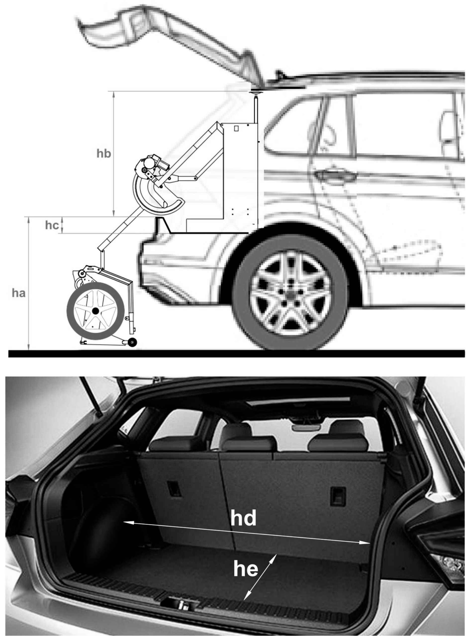
For a correct assembling of the lifter, the user must previously specify to the seller the 5 dimensions "h" of the boot of his car, shown in ( Img.2 ). Based on this information, the seller will supply the lift equipped with the appropriate components.
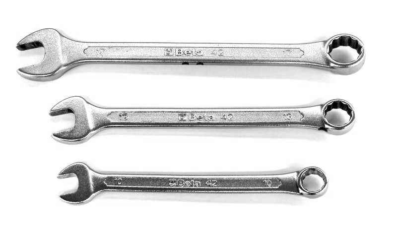
Tools required for assembling the lifter ( Img.4 )
Hexagon wrench 10 mm
Hexagon wrench 13 mm
Hexagon wrench 17 mm
SPECIFICATIONS
Weight: about 21 kg
Engine
Voltage: 24V
Max current: 3 A
The engine is powered by the same battery as the scooter. Therefore the battery is not included in the standard equipment of the lifter. On request, the lifter can be set up to power the engine also with the battery of the car on which it is installed.
DESCRIPTION
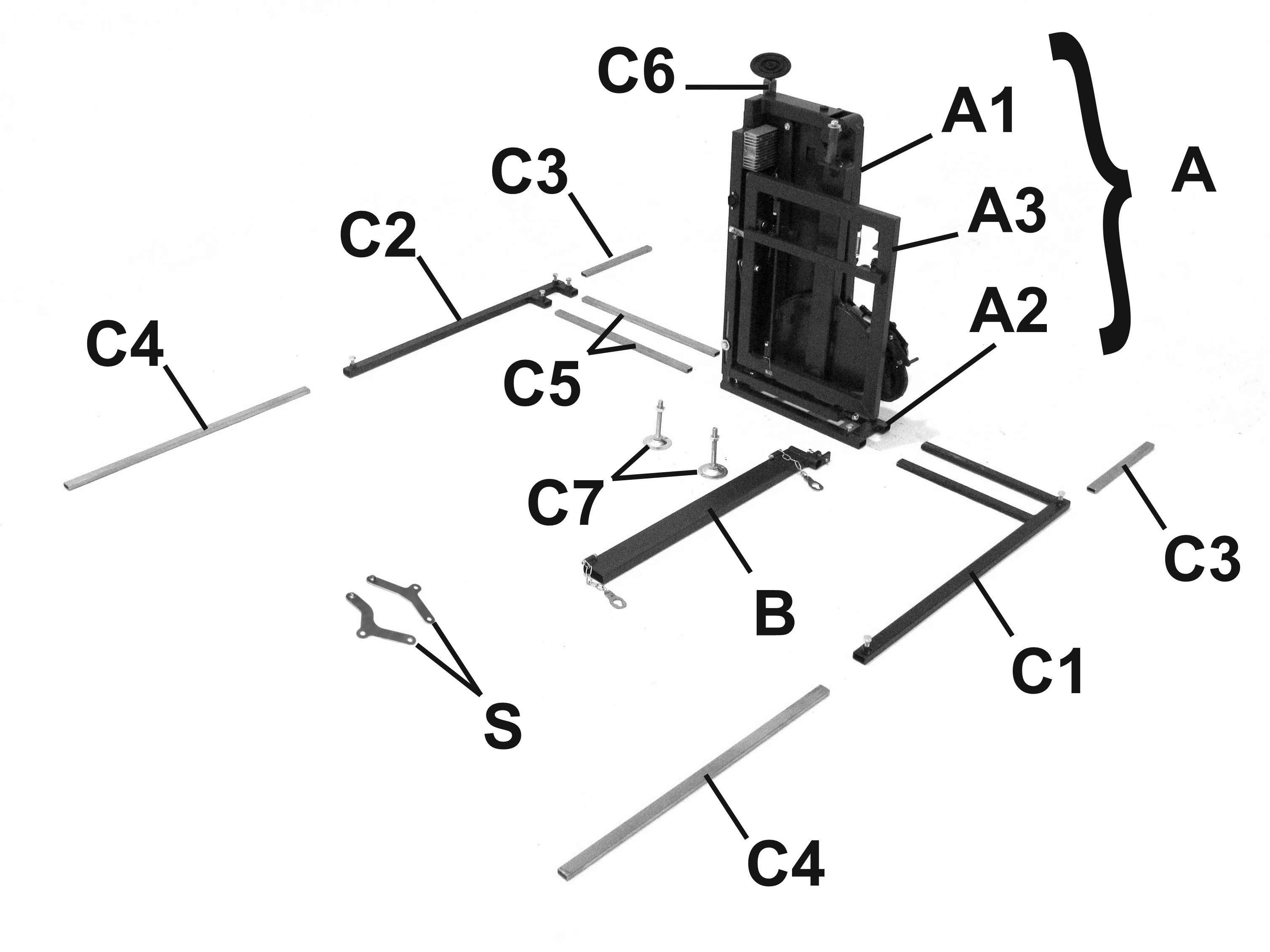
The lift essentially consists of ( Img.6 ):
The main body (A)
The lifting arm (B)
The fixing elements (C) that allow to anchor the central body to the boot and adjust its position inside it.
Two brackets (S) for connecting the lift to the scooter
The fixing elements (C) ( Img.6 ) include:
Front strut (C1)
Rear strut (C2)
Right short strut L=25cm (C3) (2 pieces)
Left long strut L=45cm (C4) (2 pieces)
Rear strut longitudinal extension (C5) (2 pieces)
Vertical strut (C6)
Strut (C7) of the folding frame (A3) (2 pieces)
Depending on the "hc" and "he" dimensions of the boot ( Img.2 ), the seller will supply the extensions (C5) and the struts (C7) with the following dimensions:
|
he |
C5 |
|
<75cm |
25 cm |
|
> 75cm |
55 cm |
|
hc |
C7 |
|
0 - 9 cm |
9 cm |
|
10 - 14 cm |
14 cm |
|
15 - 18 cm |
18 cm |
INSTALLATION OF THE LIFTER IN THE BOOT
Place the main body of the lifter on a work surface.
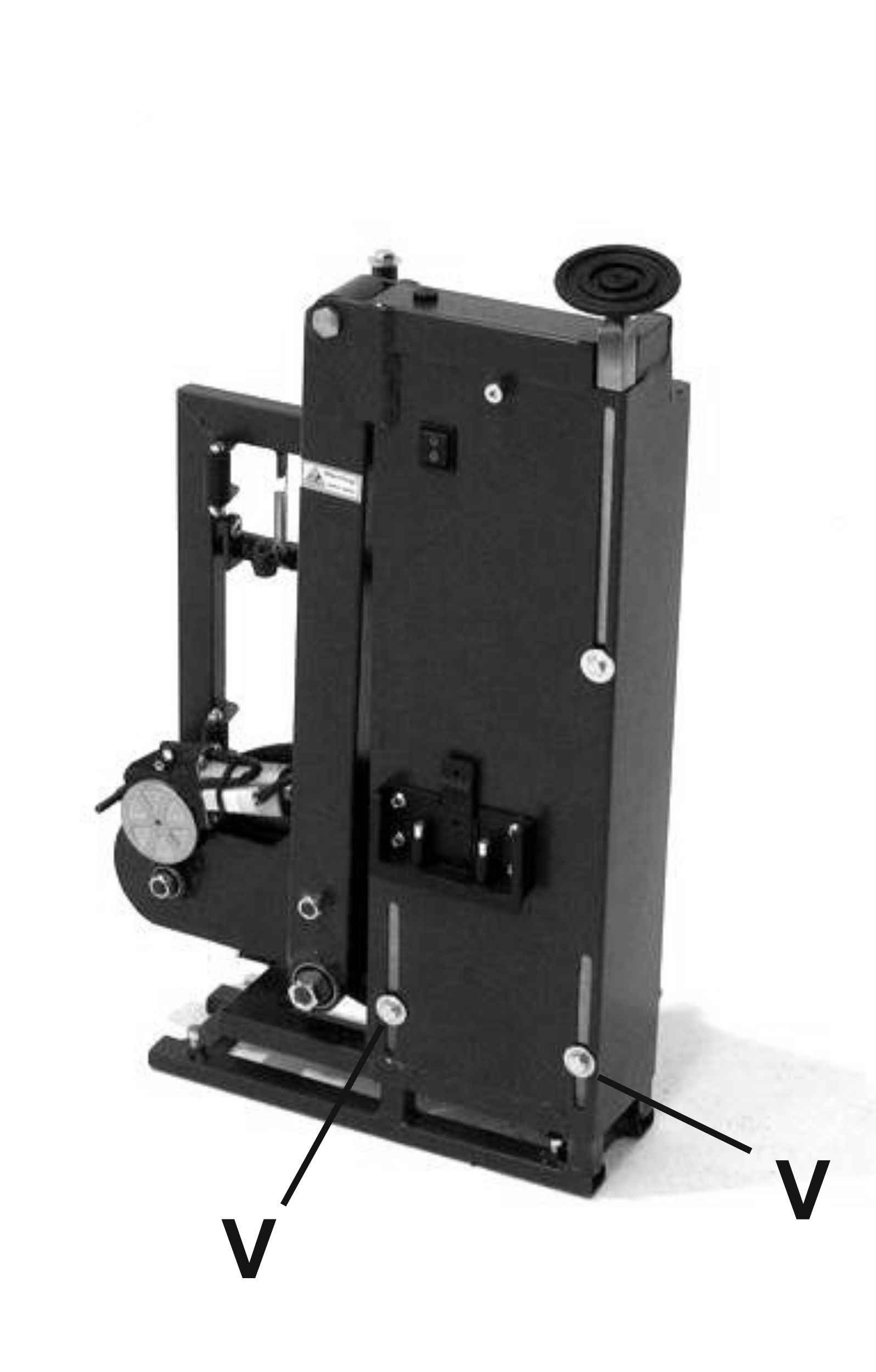
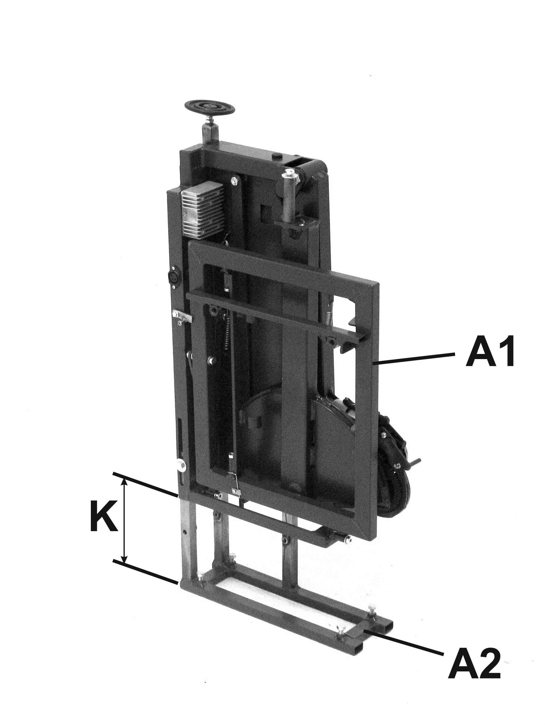
Loosen the three screws (V) ( Img.12 + Img.13 ), raise the upper frame (A1) with respect to the base frame (A2) until the height (k) ( Img.14 ) is at least 2 cm greater than the height (hc) ( Img.2 ) of the rear edge of the boot. Then tighten the three screws (V) ( Img.12 + Img.13 ).
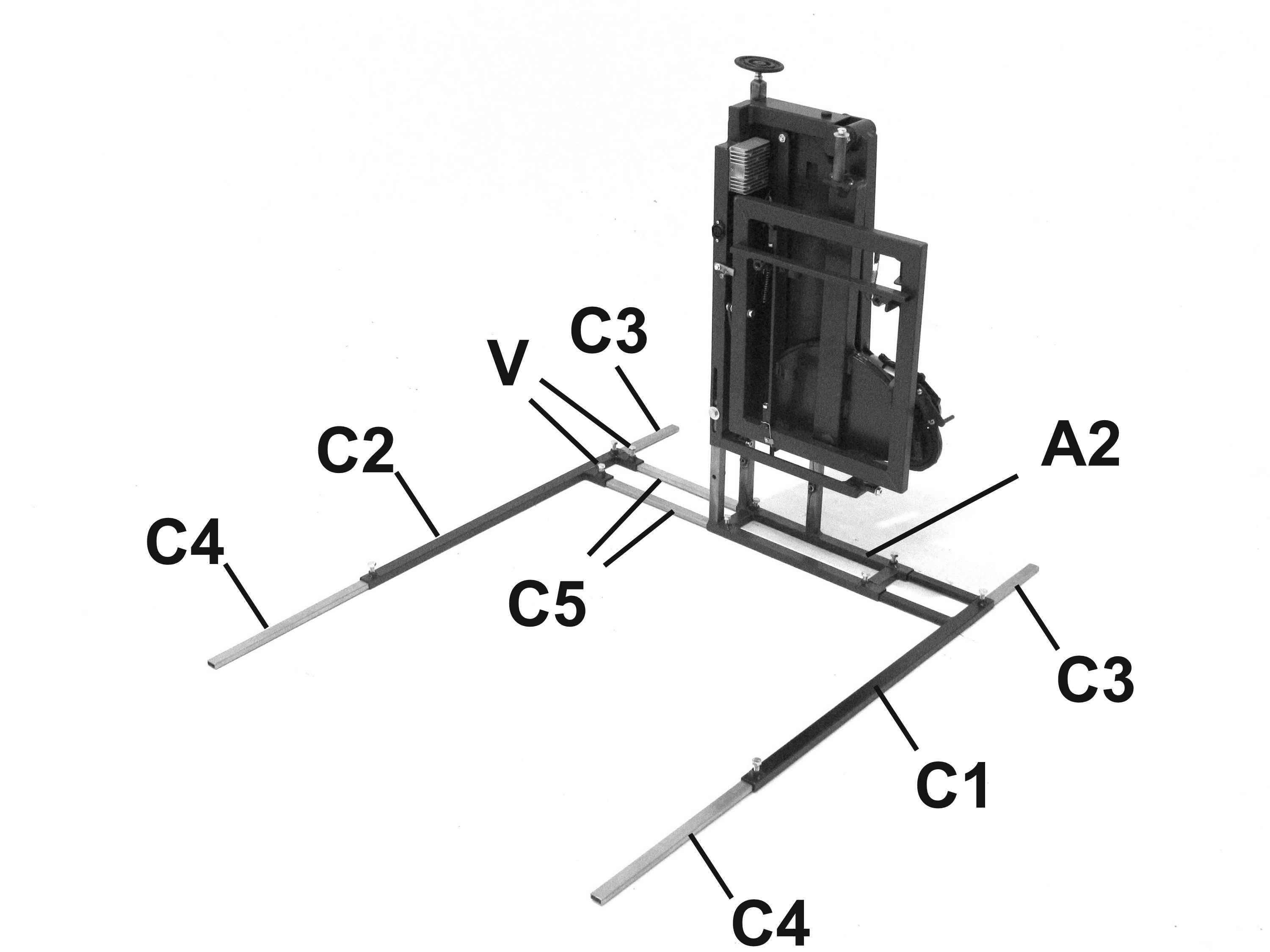
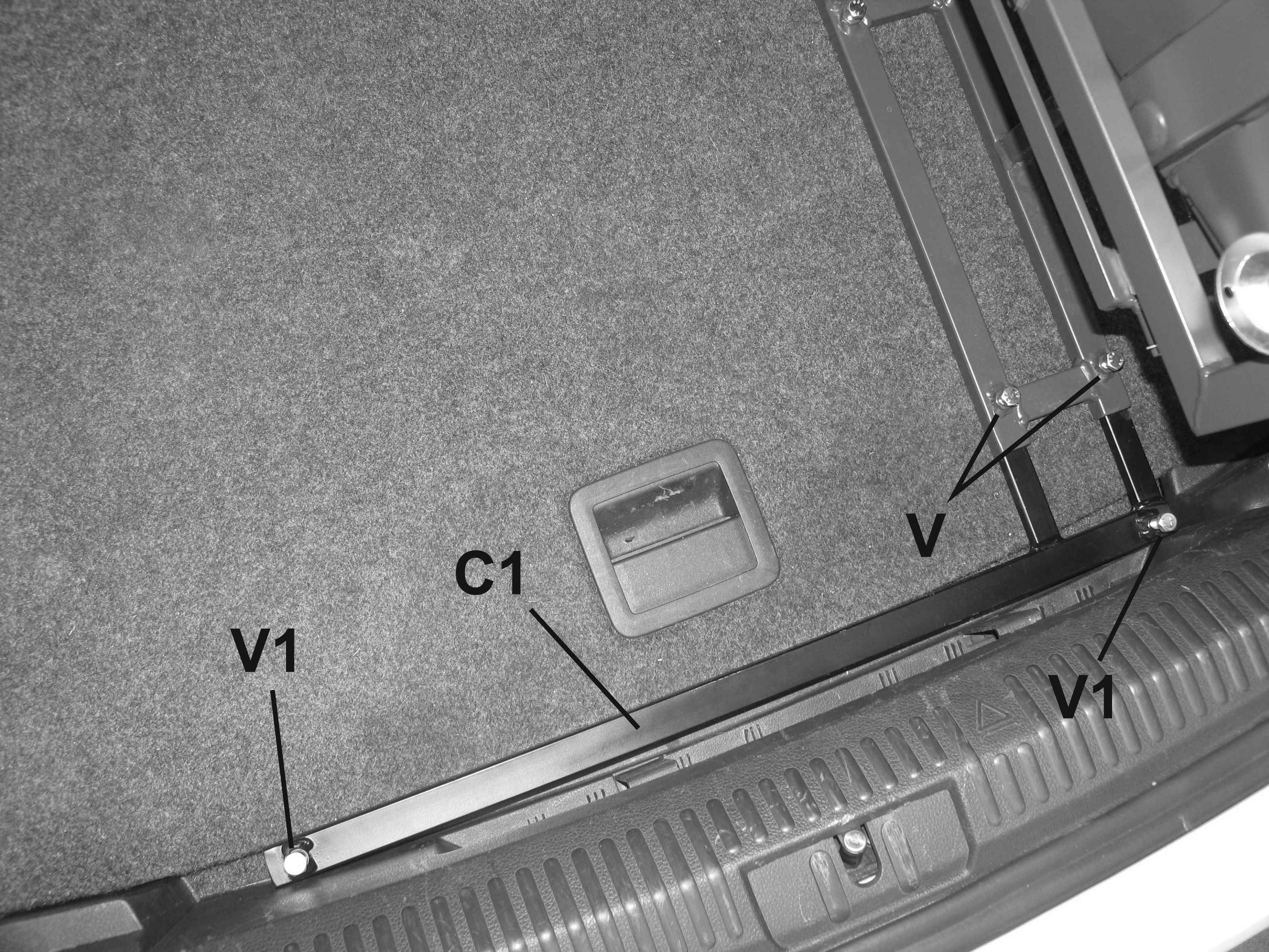
Insert completely the front strut rods (C1) into the front end of the base frame tubes (A2) ( Img.20 ). If the boot has no rear edge (hc = 0) ( Img.2 ), insert the short strut (C3) completely inside the right end of the strut (C1) and insert the long strut (C4) completely inside of its left end ( Img.20 ).
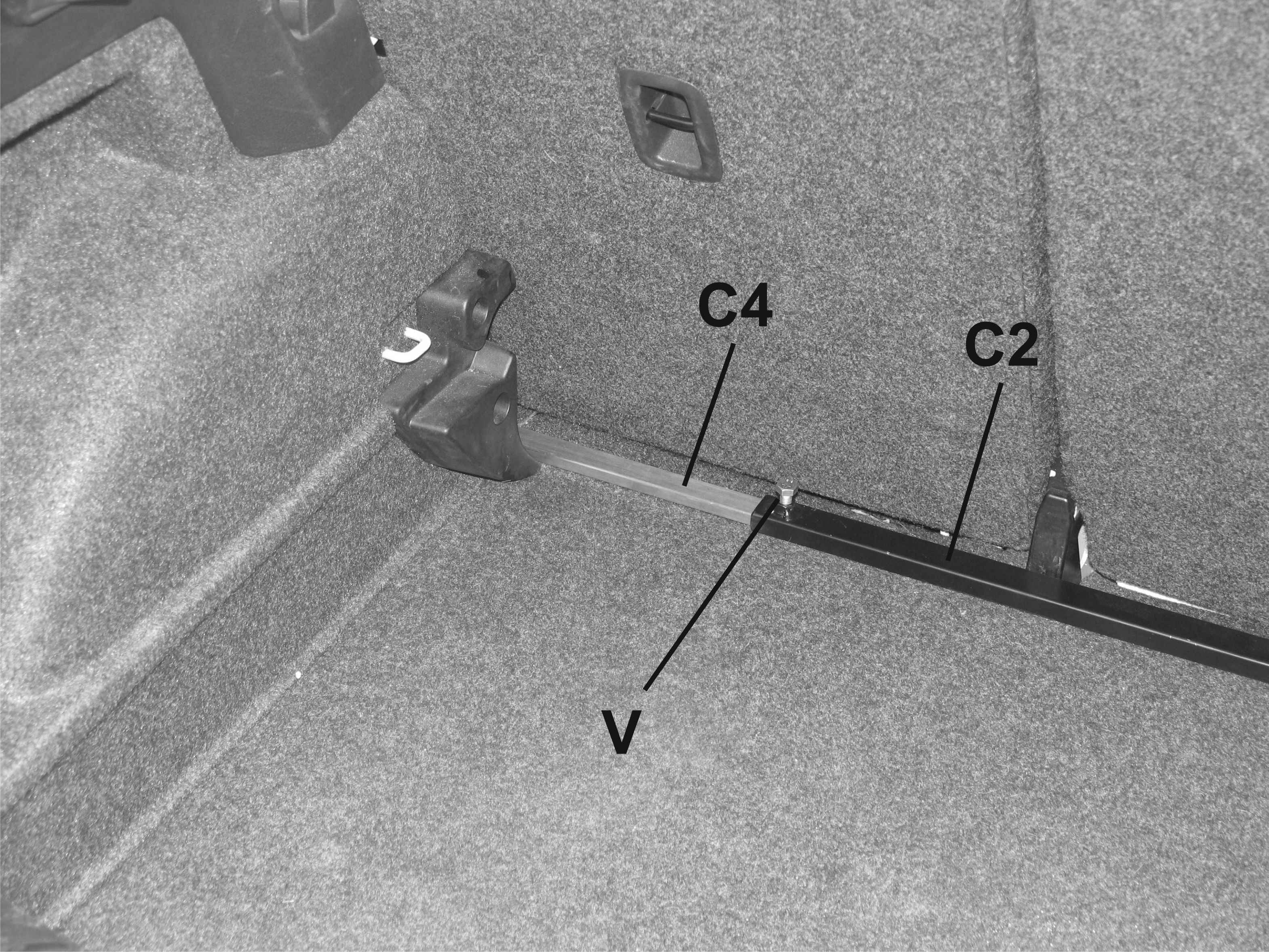
Insert completely the short strut (C3) inside the right end of the rear strut (C2) and insert the completely long strut (C4) inside the left end of the strut (C2) ( Img.20 )
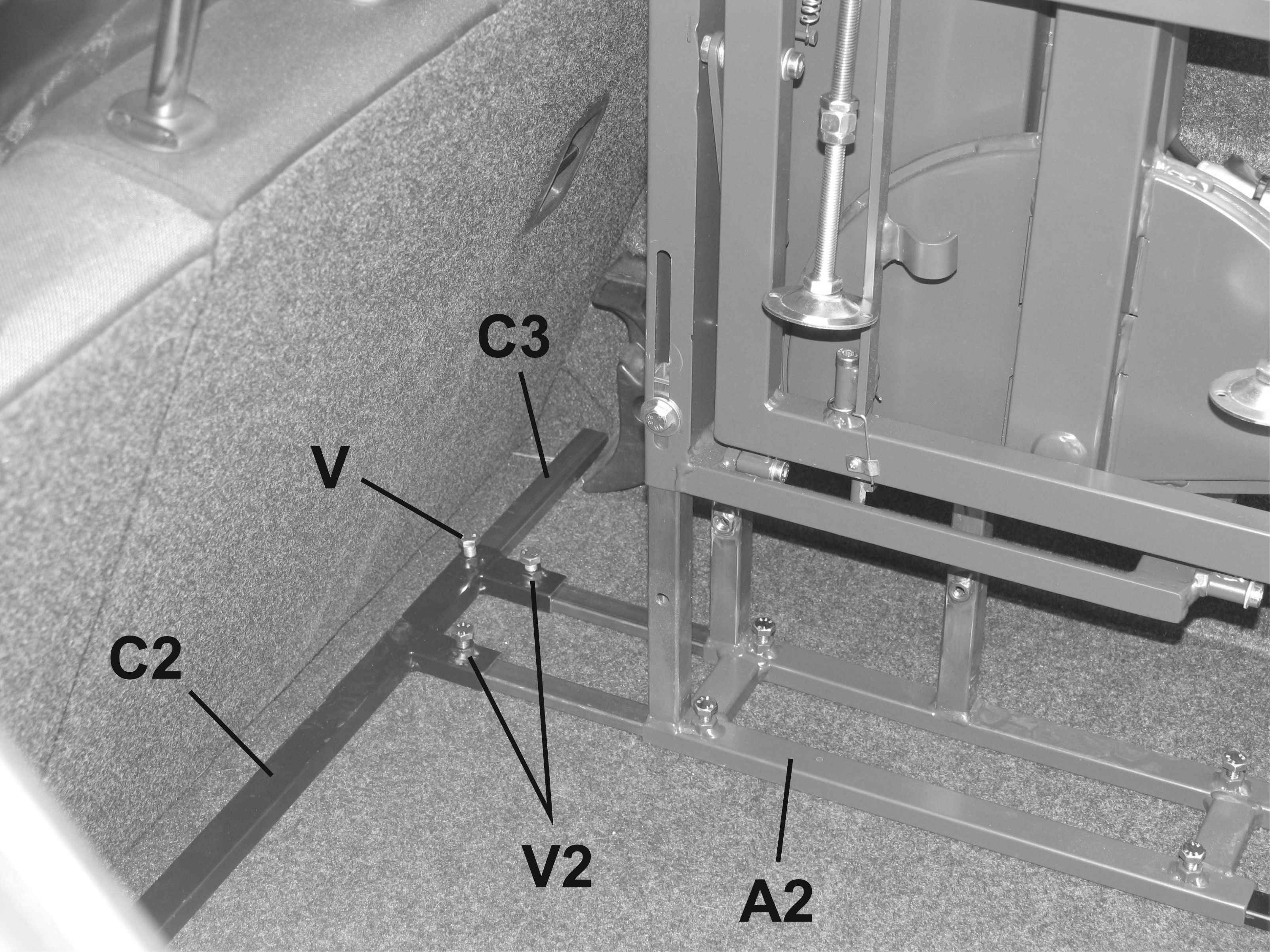
Insert completely the longitudinal extensions (C5) into the rear strut (C2) and lock them by tightening the screws (V) ( Img.20 ). Then insert completely the extensions (C5) inside the rear end of the base frame tubes (A2) ( Img.20 ).
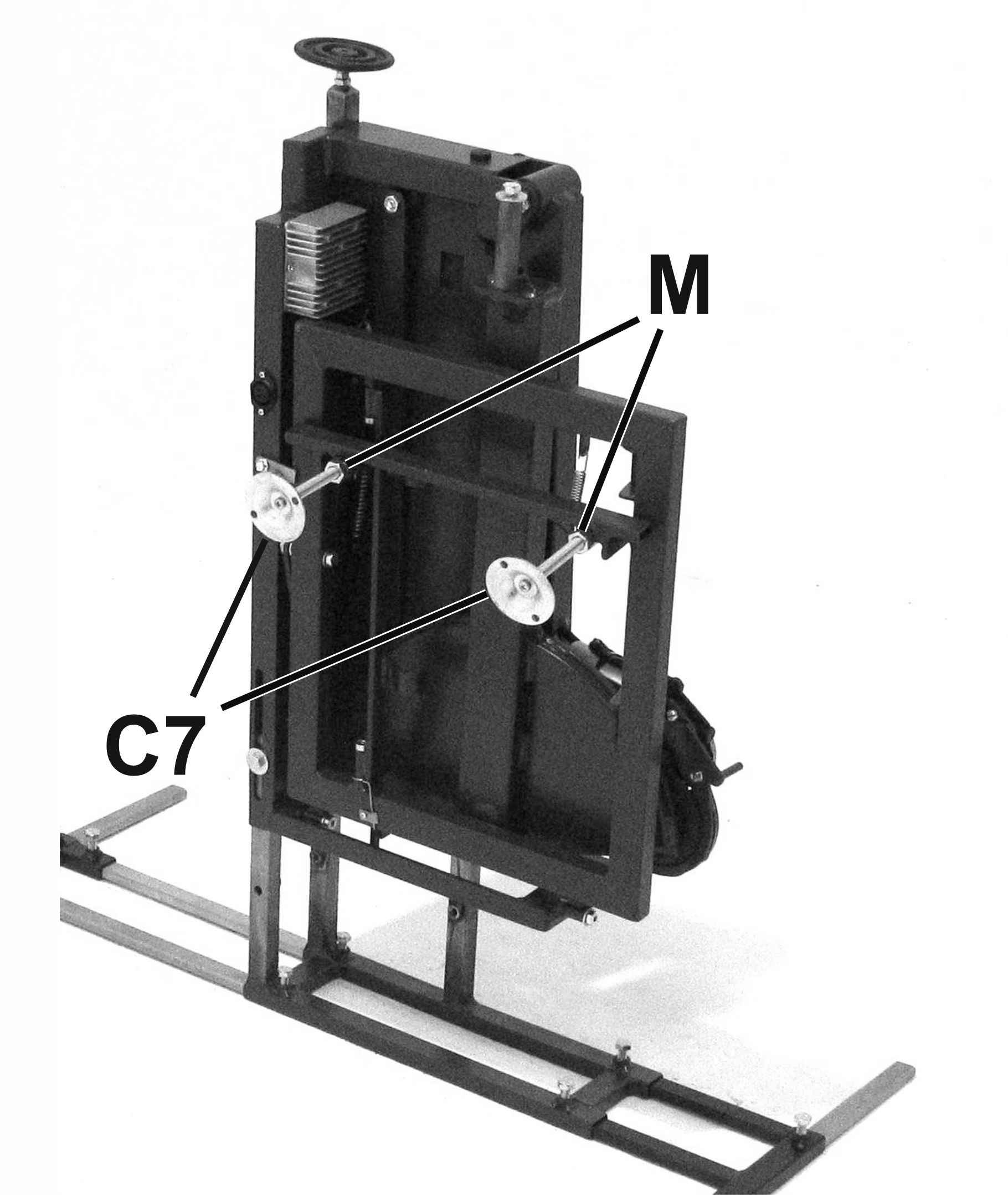
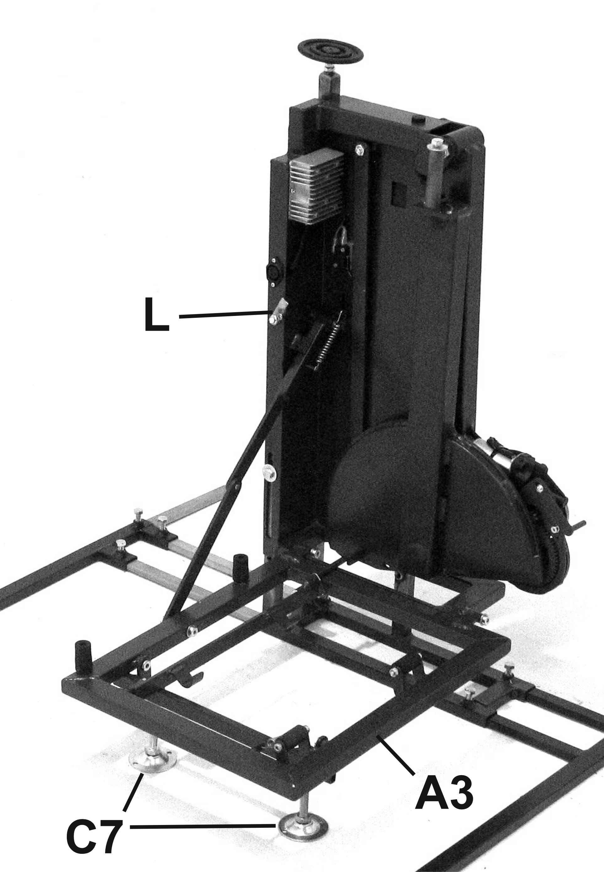
Screw the screws of the two struts (C7) into the folding frame (A3) ( Img.25 ) and lock them with the relevant lock nut (M) ( Img.25 ).
Unlock the folding frame (A3) by turning the lever (L) ( Img.30 ), then lower it until it is locked in a horizontal position. Check that the bottom of the struts lay firmly on the floor: otherwise, screw or unscrew, as necessary, the strut screws (C7), taking care to always lock them with the relevant lock nut (M).
Check that the two rods (T) are slightly misaligned as shown in ( Img.31 ) which ensures the locking of the folding frame in a horizontal position
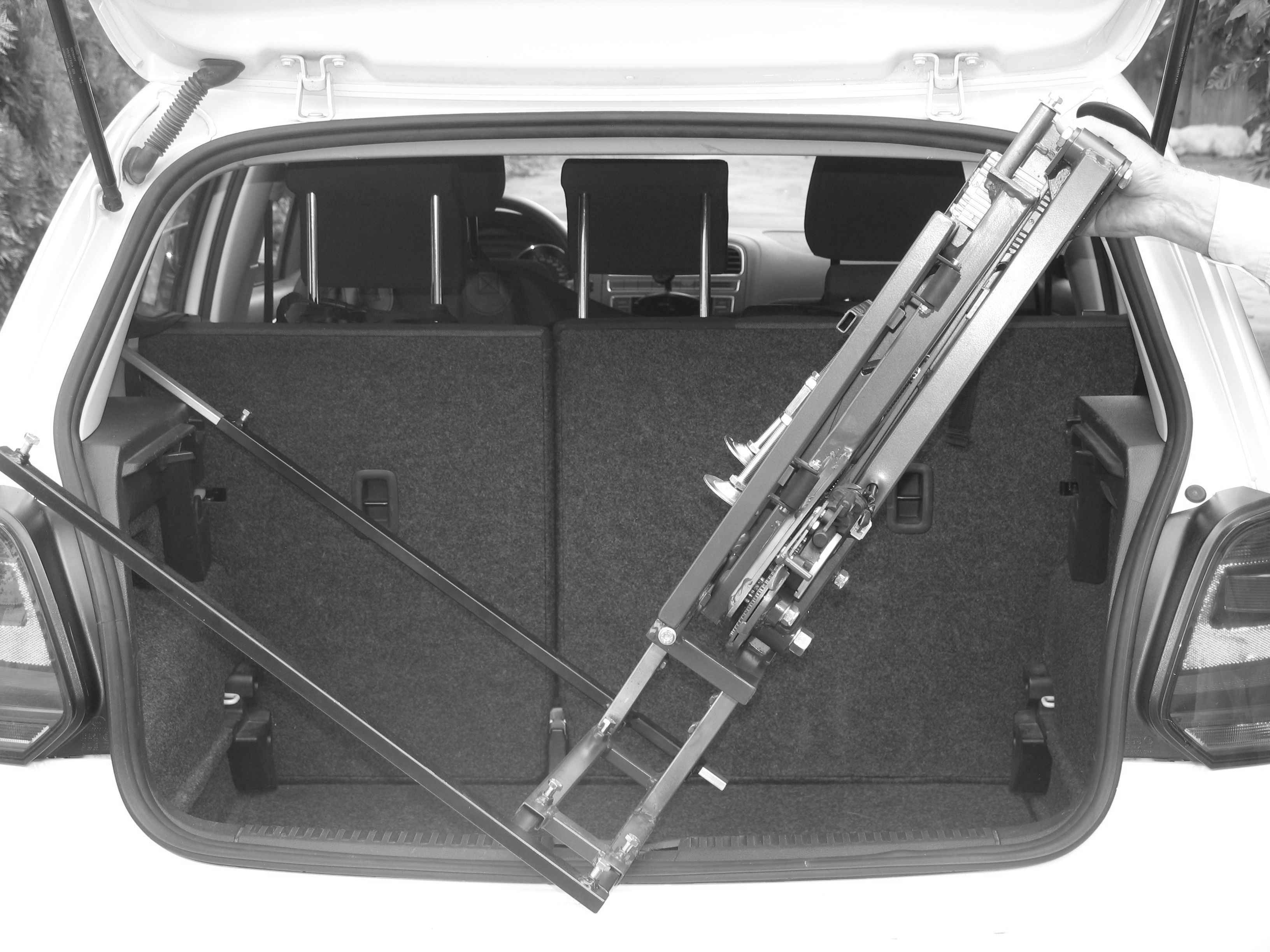
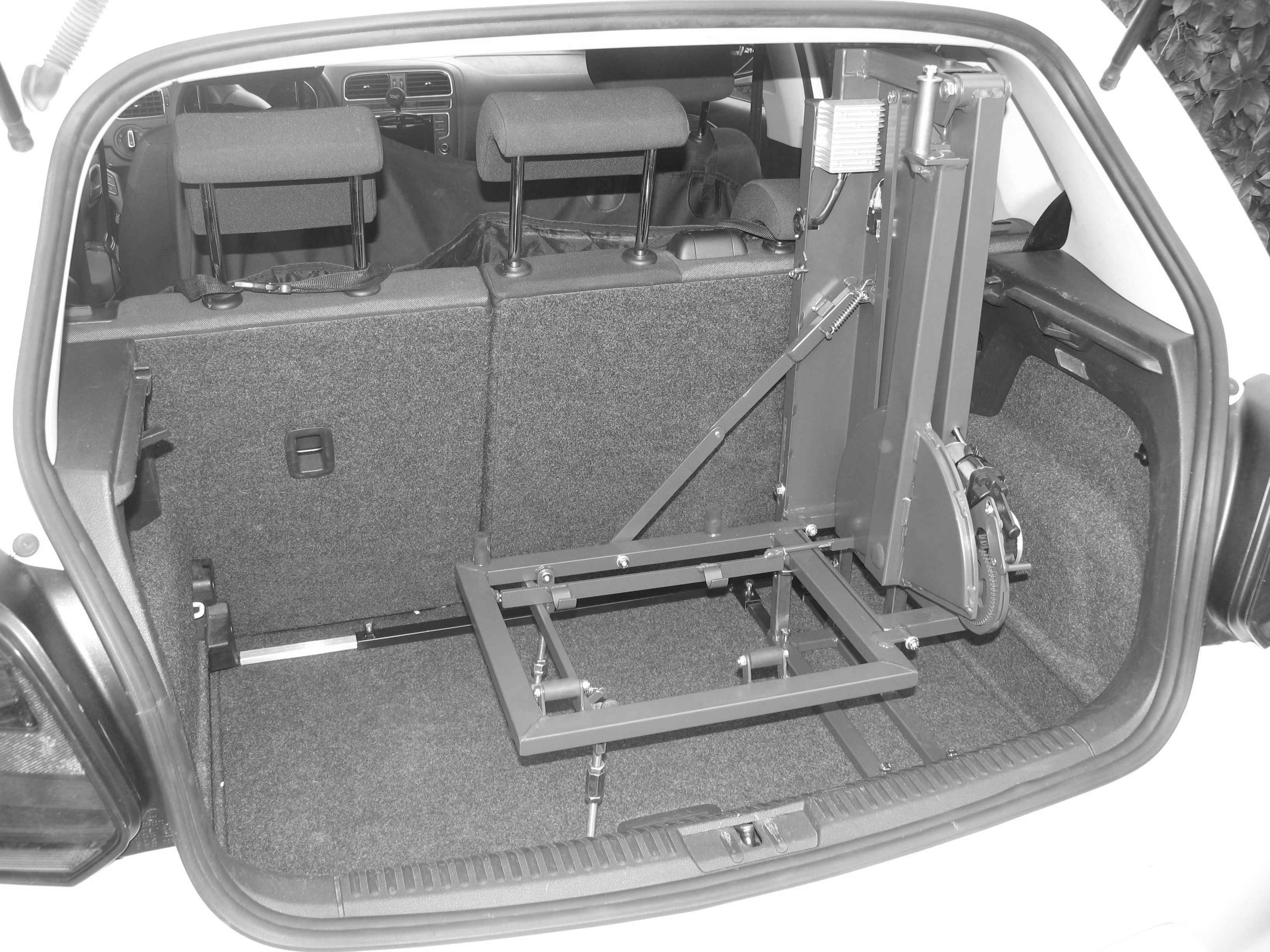
Place the lifter in the car boot ( Img.34 + Img.35 + Img.36 ) with the rear edge parallel to the back side of the car seat. Check again that the two rods (T) are misaligned as shown in ( Img.31 ).
Position the lifter transversely so that there is enough space between the right side of the boot and the right side of the lifter so to allow the battery to be inserted. ( Img.40 ) ( Img.75 )
Pull out the rear strut (C2) until it comes into contact with the the back side of the car seat ( Img.44 ) and extend the right (C3) and left (C4) cross struts mounted in the rear strut (C2) until the respective free ends go to contact respectively with the right ( Img.44 ) and left walls of the boot ( Img.45 )
Pull out the front strut (C1) until it
comes into contact with the rear side of the boot edge ( Img.50
).
If the boot has no rear edge (hc = 0) ( Img.2
), extend the right (C3) and left (C4) cross struts mounted in the
front strut (C1) (See Par. 5c) until their respective free ends
come into contact respectively with the right and left walls of the
boot and at the same time lay on the rear sides of the relevant
rear door posts.
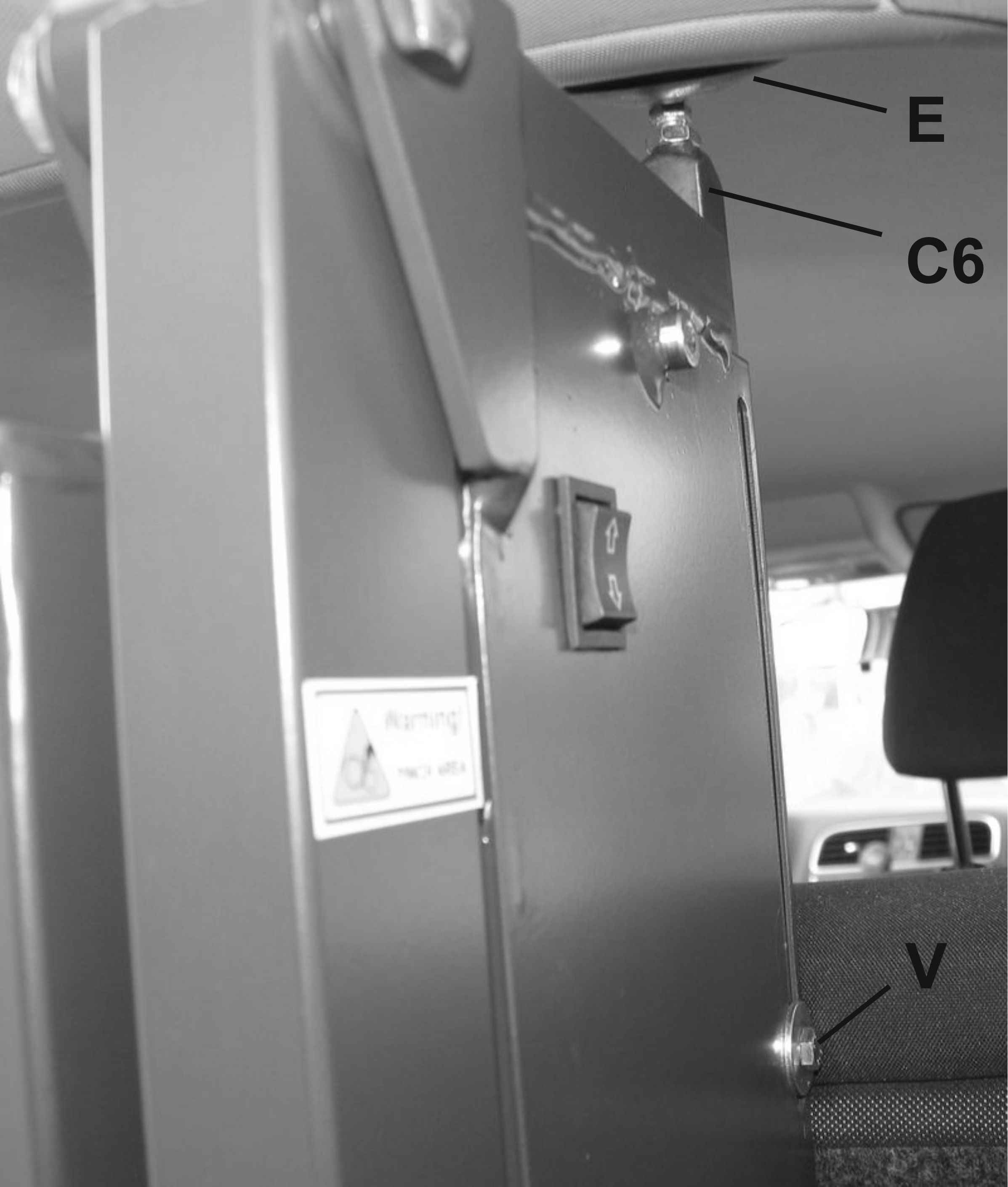
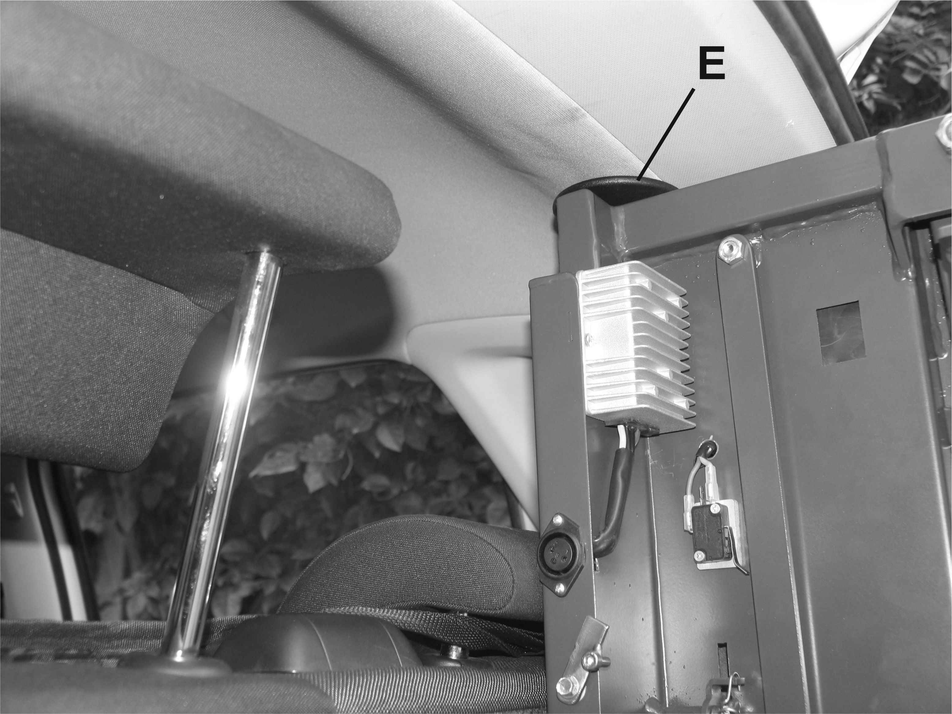
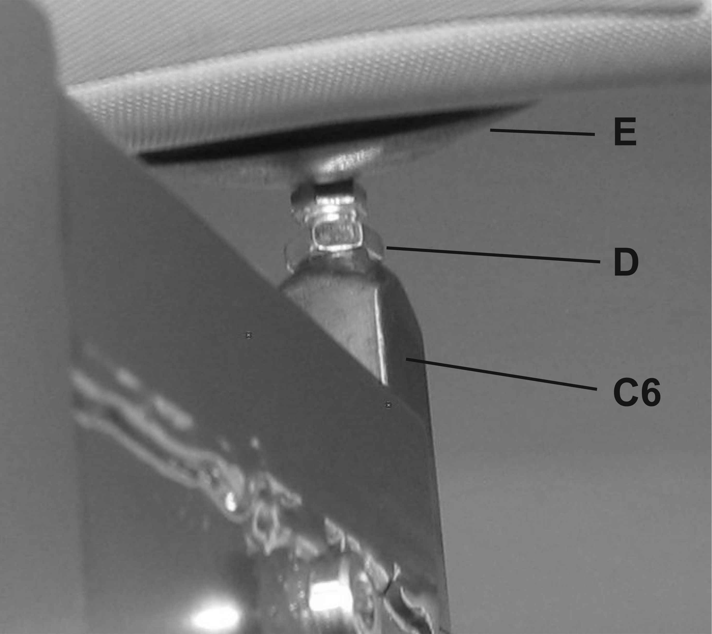
Lift the vertical strut (C6) so as to
bring the support disk (E) into contact with a sufficiently flat
part of the boot roof ( Img.54 ) (
Img.55 ) Then tighten the locking
screw (V) ( Img.54 ).
Further
adjustment of the disc pressure on the roof can be obtained by
unscrewing the locking nut (D) ( Img.56
) below the disc, unscrewing the disc (E) and locking again the
locking nut (D). The maximum adjustment that can be made by
unscrewing the disc screw is about 2 cm.
By means of these two
adjustment means, it is necessary to reach a full contact of the
disc (E) to the roof of the boot.
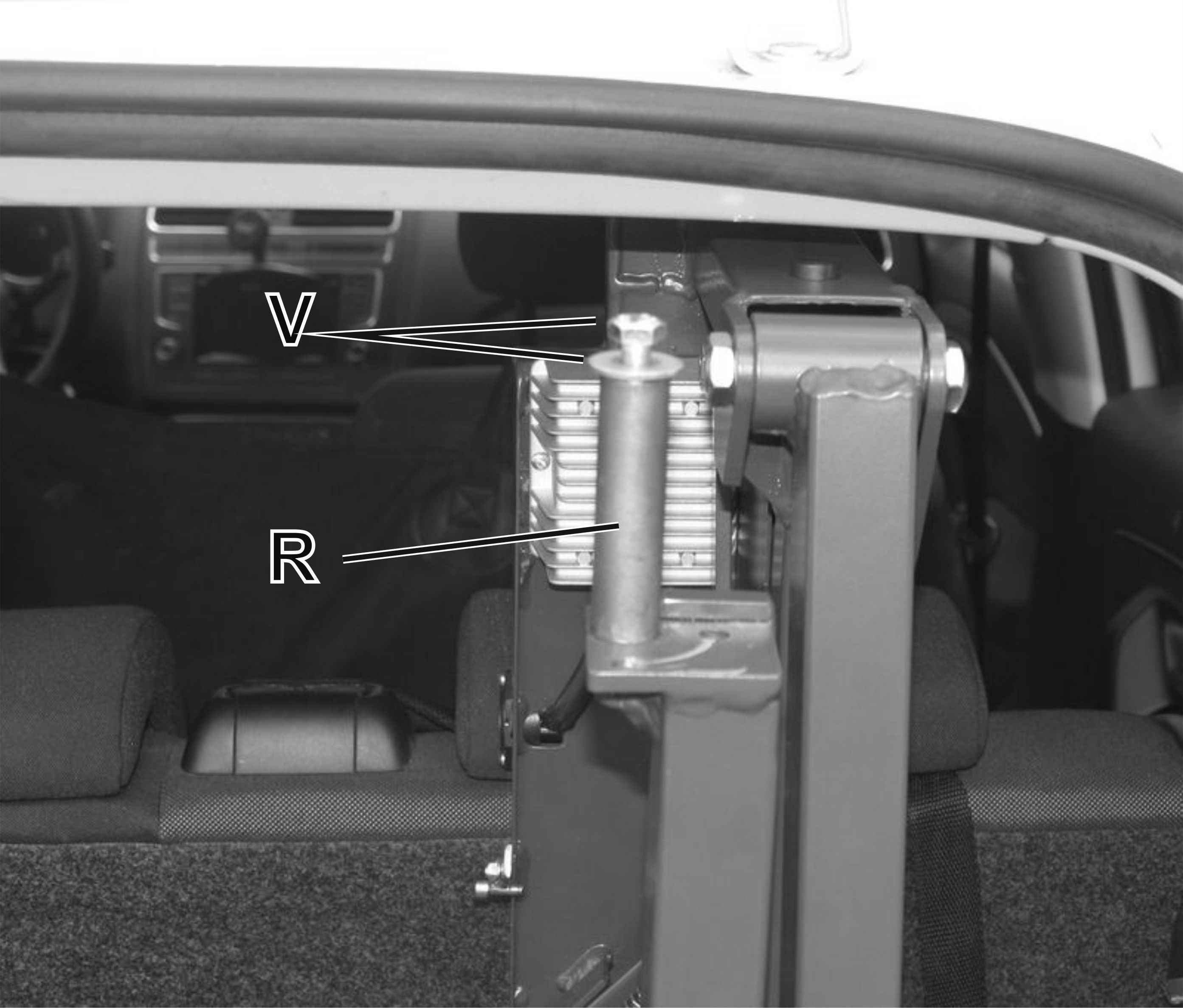
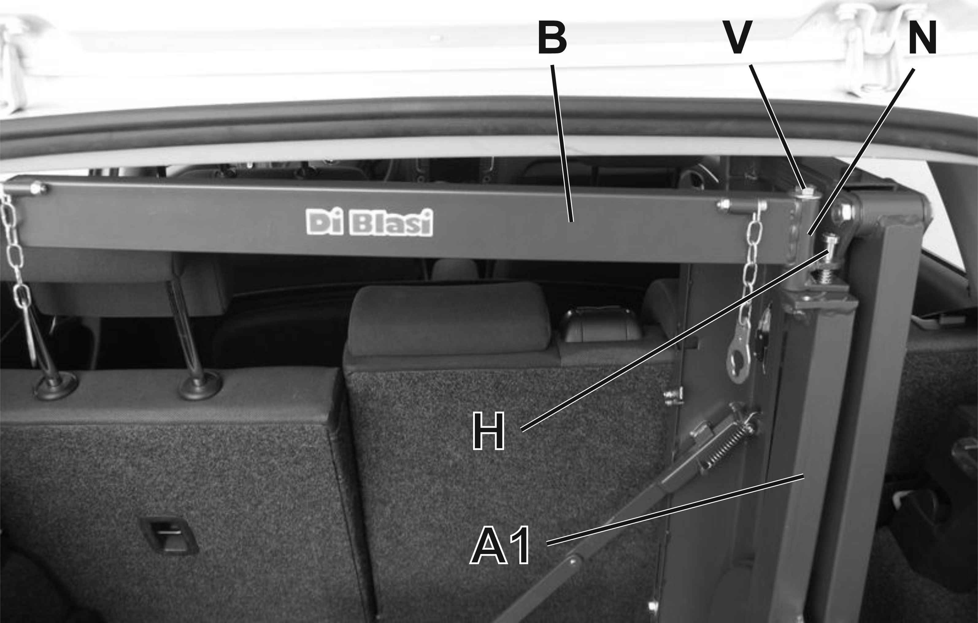
Remove the screw and the washer (V) ( Img.60 ), insert the pin (R) in the end (N) of the arm (B), screw and tighten the screw and the washer (V) ( Img.61 ). Position the arm (B) so that the lower end of the pin (H) fits into the hole made in the below frame (A1): this prevents the arm (B) from rotating around the pin (R)
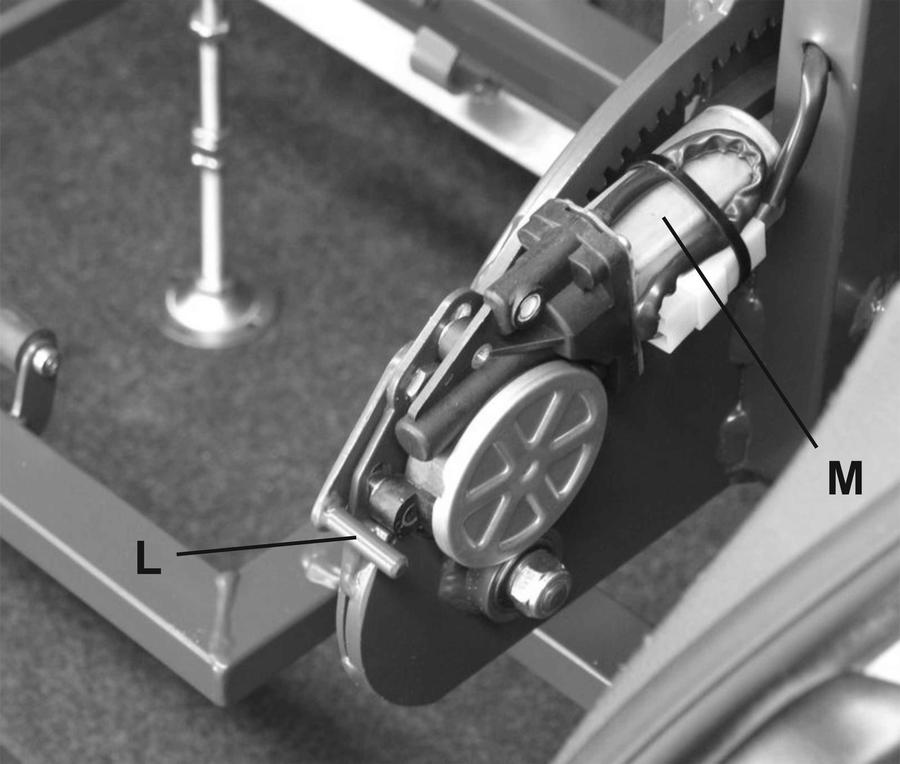
Unlock the gearmotor that activates the lifter ( Img.65 ):
Raise the lever (L)
Lower the rear part of the engine (M)
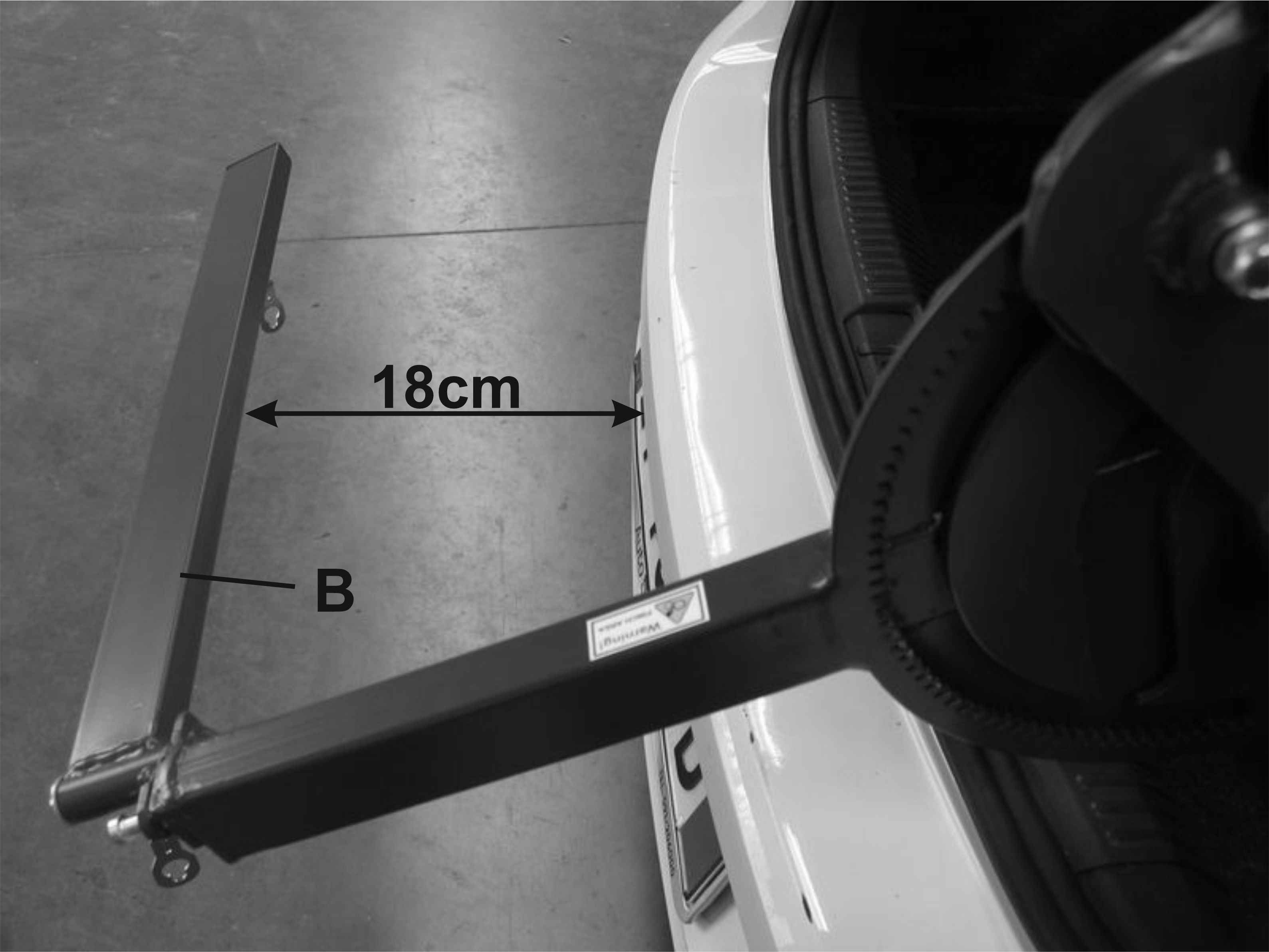
Extend manually the lifter until the arm
(B) is at the same height of the most protruding outer edge of the
car and check that there is a distance of at least 18 cm between
this edge and the inner edge of the arm (B) ( Img
.70 )
If the distance is less than 18cm:
Push backward the lifter but so that the front (C1), rear (C2), right (C3) and left (C4) struts remain in contact with the respective parts of the boot (See Sec .4k and 4l)
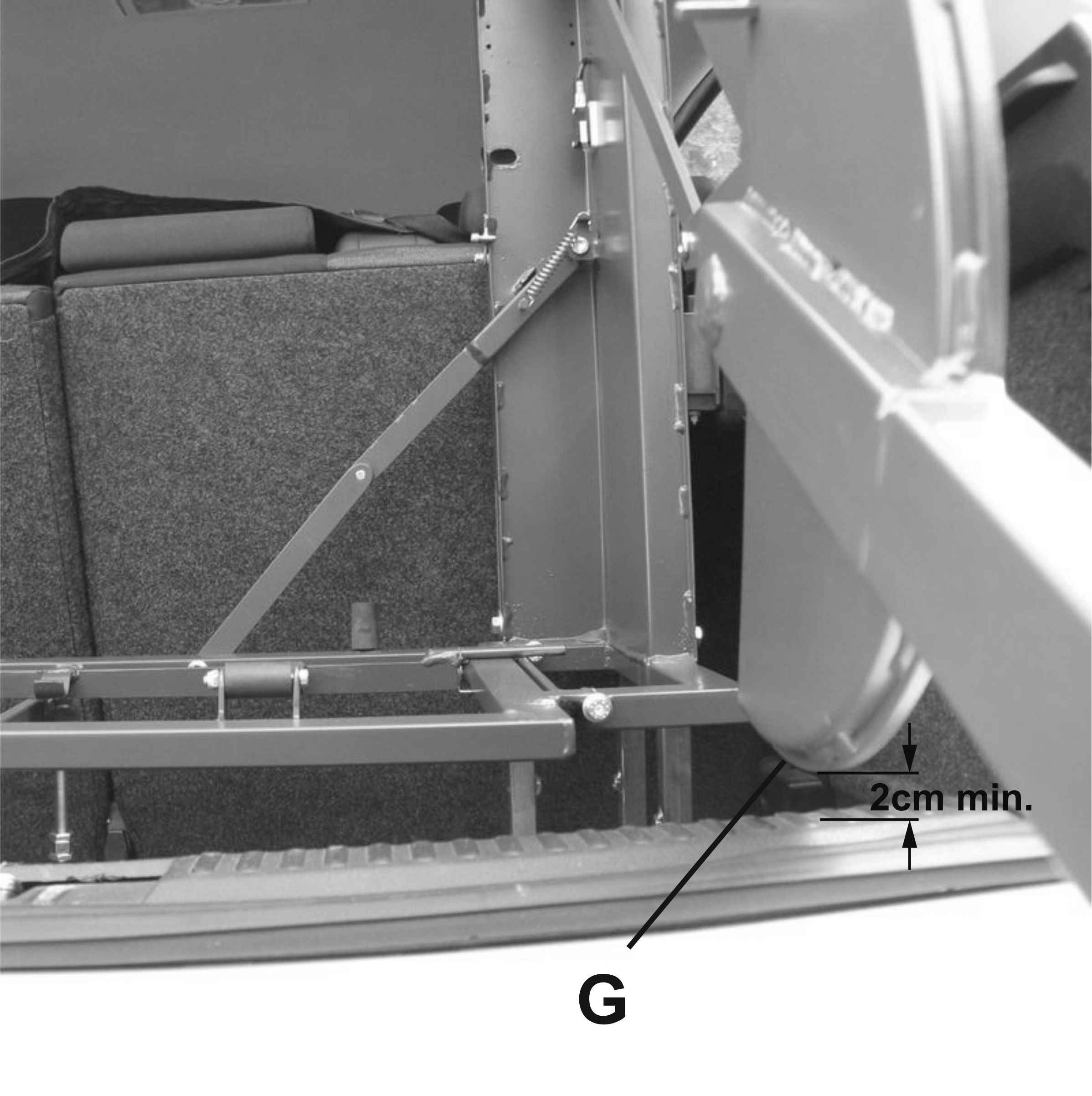
Check that there is a distance of at
least 2 cm between the edge (G) of the lifter and the rear edge
of the boot ( Img.72 ).
If this distance is less than 2cm:
Loosen the locking screw (V) and lower the vertical strut (C6) ( Img.54 )
Loosen the three screws (V) ( Img.14 + Img.15 ), raise as necessary the upper frame (A1) with respect to the base frame (A2) ( Img.14 ), tighten the three screws (V) ( Img.14 + Img.15 ),
Repeat the operation described in Sec. 4m)
Retract manually the arm of the lifter and then:
check that the front (C1), rear (C2), right (C3) and left (C4) struts remain in contact with the respective parts of the boot (See Sec. 4k and 4l)
tighten the screw (V2) of the rear strut (C2) ( Img.44 )
tighten the screws (V) of the right and left cross struts (C3) and (C4) mounted in the rear strut (C2) ( Img.44 ) and ( Img.45 )
tighten the screws (V) of the front strut (C1) ( Img.50 )
if fitted, tighten the screws (V1) of the right (C3) and left (C4) cross struts mounted in the front strut (C1)
Make sure that the lifter is securely fixed to the boot by pushing it crosswise and lengthwise by hand.
Close and open the boot door very slowly and very carefully and check that no part of the lifter is at less than 3 cm from the closest point of the boot.
Reconnect the motor with a procedure reverse to that described in Sec. 4o)
Insert the battery of the scooter in the support on the right side of the lifter ( Img.75 )
Press "down arrow" on button (P) ( Img.75 ) with very short pulses and at each pulse check that no moving element of the lifter is at less than 3 cm from the boot or the door boot.
Drive the car for a short trip including curves and breakings and then check that the lifter remains firmly blocked in the boot.
When the scooter is not loaded in the lifter, it is possible to increase the free space available in the boot by turning the arm (B) towards the inside of the car after having released the pin (H) ( Img.61 ) from the below frame (A1) ( Img.61 )
FITTING OF THE LIFTING BRACKETS IN THE SCOOTER
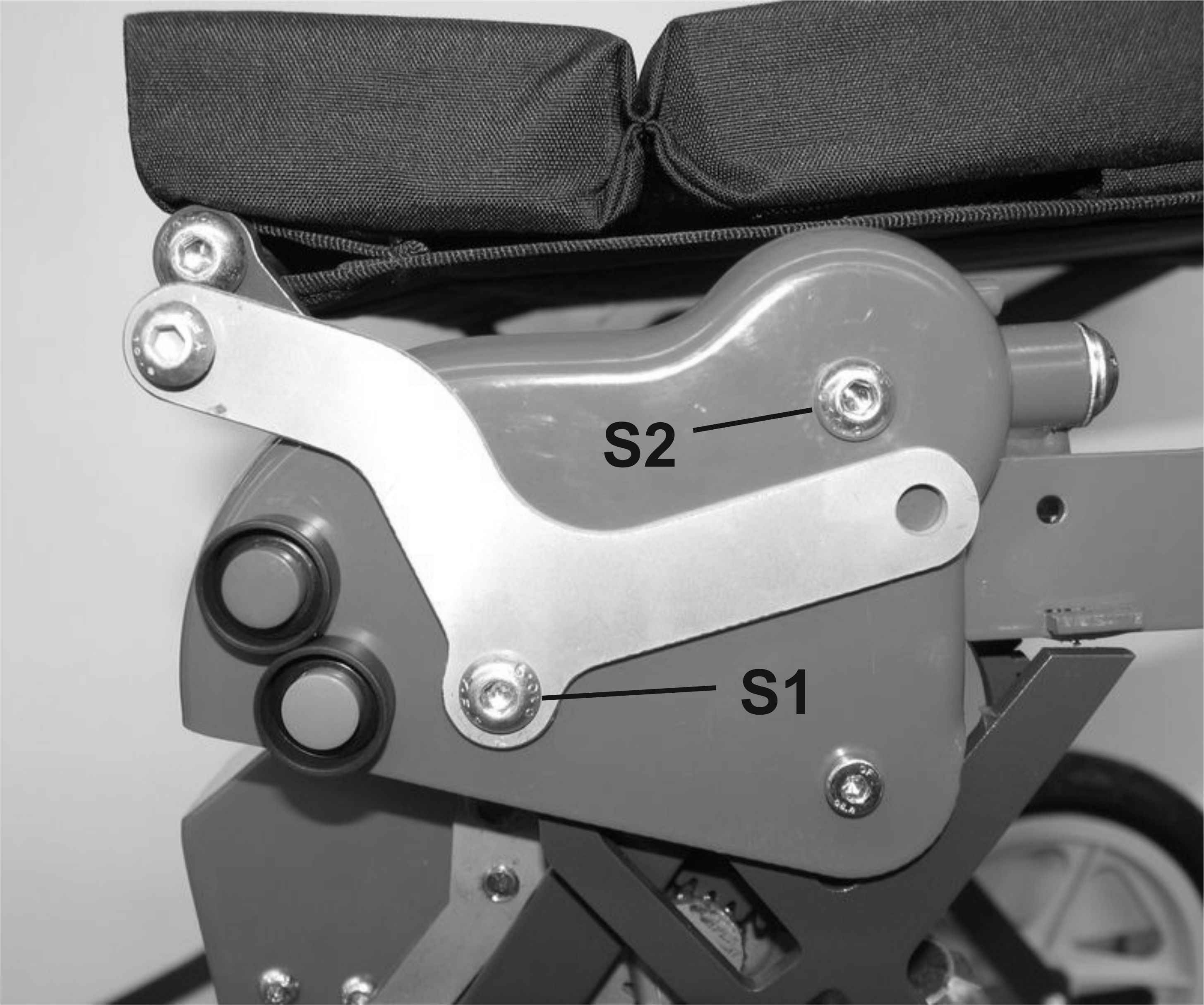
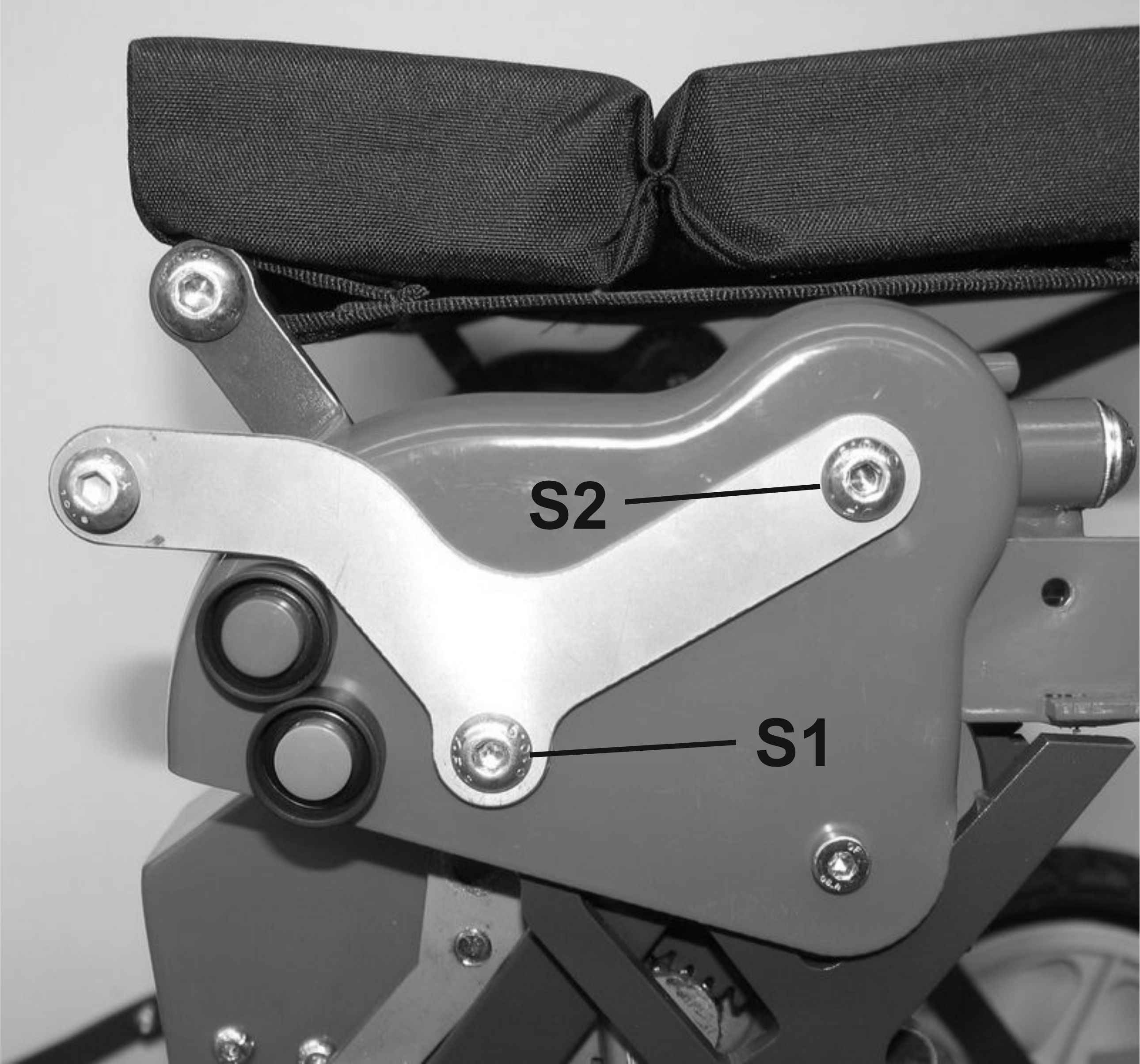
Remove the screw (S1) of the scooter ( Img.80 ). In some versions of the scooter, the screw (S1) is screwed to a nut placed inside: in this case, unscrew the screw keeping this nut locked.
Place the bracket (S) as shown in ( Img.81 ), screw the screw (S1) without tightening.
Remove the screw (S2)
Move the plate (S) so that the remaining hole coincides with the screw hole (S2), then screw and tighten the screws (S1) and (S2) ( Img.82 )
Fit the second bracket (S) on the other side of the scooter.
TO LOAD THE SCOOTER IN THE TRUNK
Important safety warnings
When loading and unloading the scooter, stay away as far as possible from the lifter ( Img.100 ).
When pressing the button (P) ( Img.75 ) ensure your fingers and the other hand are kept away from the surrounding area to prevent them from being pinched/injured in the lifting mechanism.
Keep loose clothing (such as ties, scarves, etc.) or long hairs away from the lifting mechanism as they could get entangled and you could be injured.
Insert the battery of the scooter in the support of the lifter ( Img.75 )
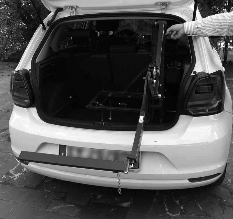
Extend the lift arm ( Img.100 ) by keeping pressed "arrow down arrow" of the button (P) ( Img.75 )
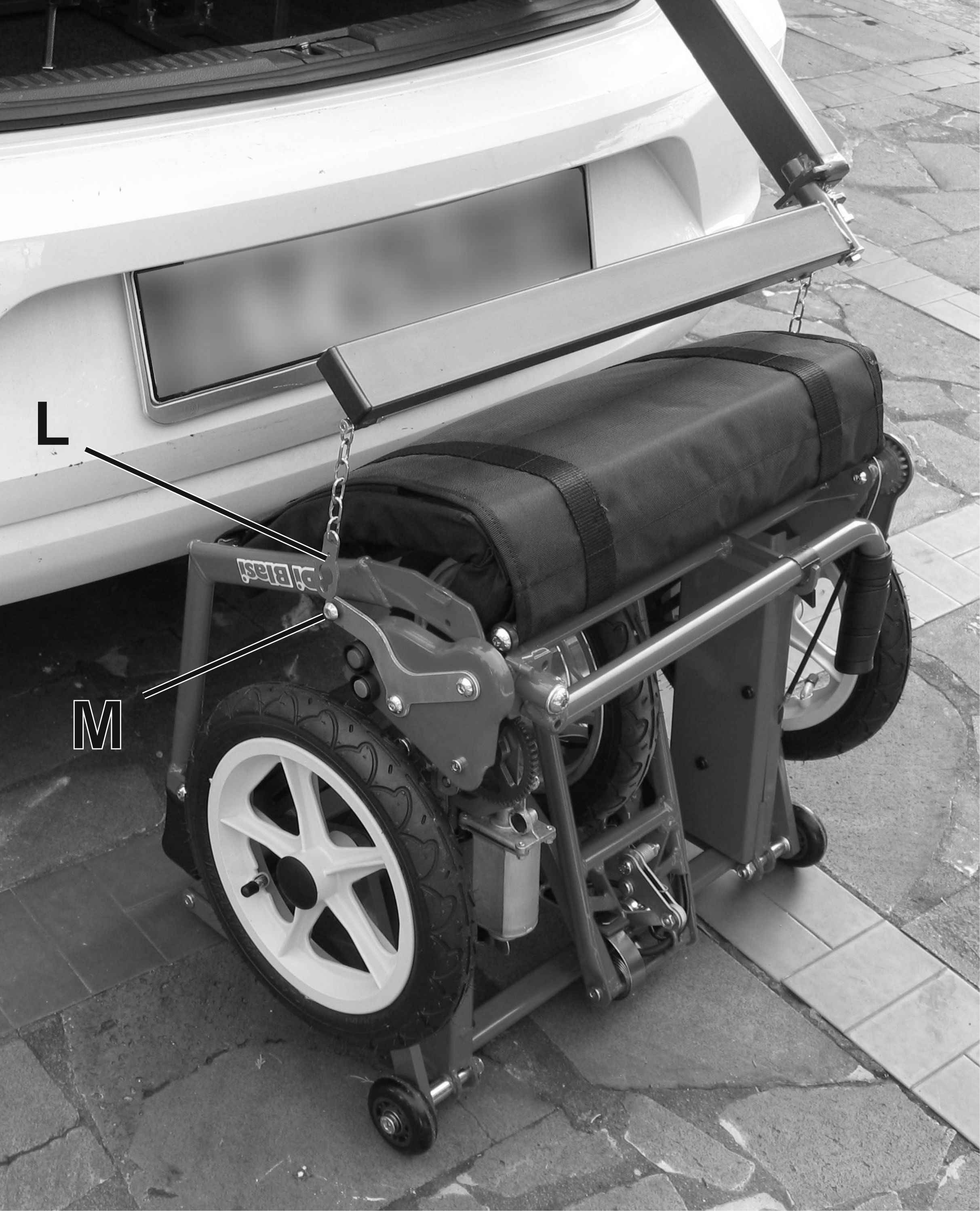
Fold the scooter and place it so that the back rest faces the boot ( Img.104 ) and that the rings (L) at the lower ends of the lifting chains are close to the pins (M) on the side of the scooter ( Img.106 ).
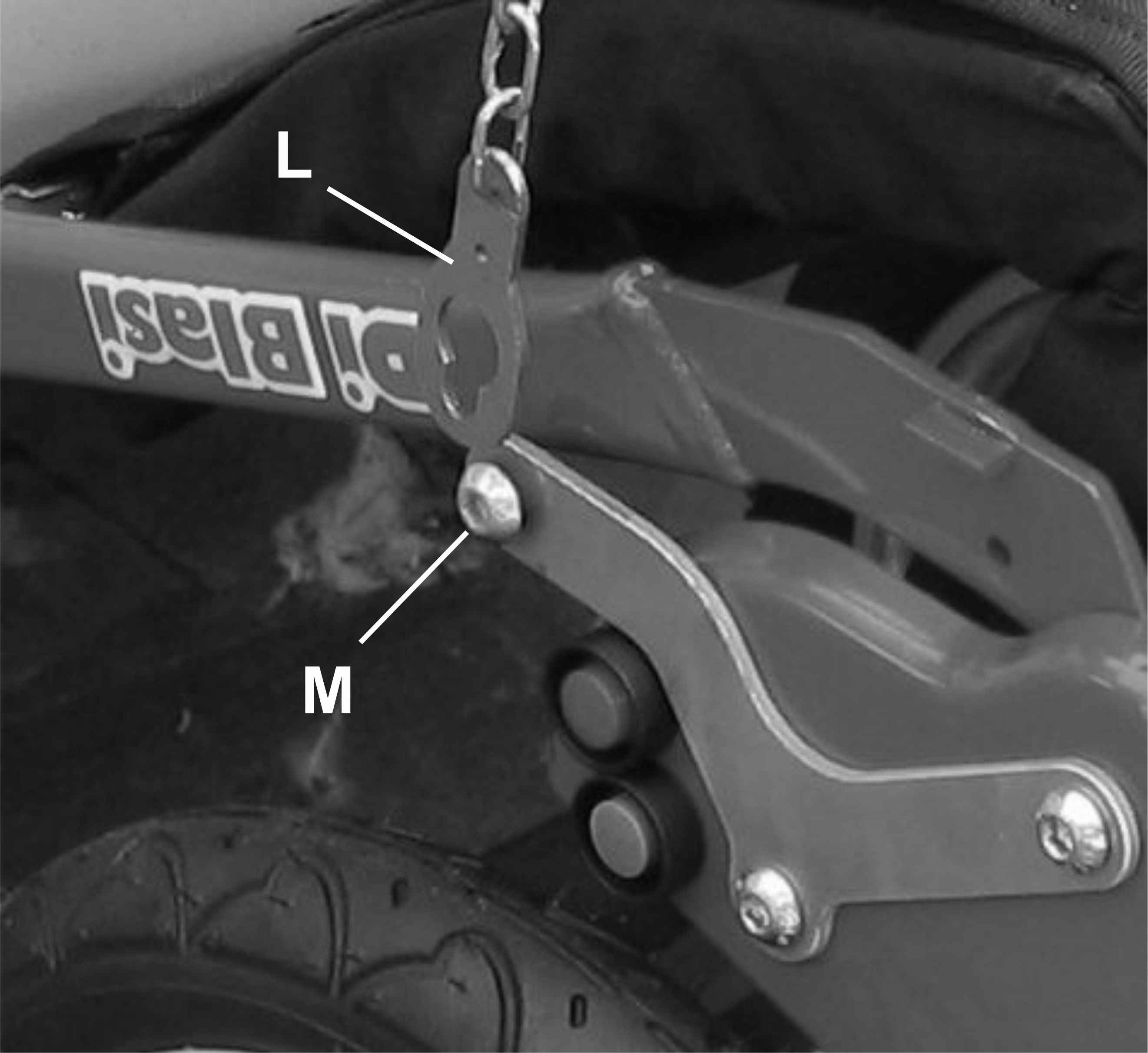
On both sides of the scooter, hook the ring (L) into the pin (M): insert the pin (M) in the larger part of the ring hole (L) ( Img.108 ) and then move the ring so that the narrow part of the hole prevents it from coming out ( Img.110 ).
Press shortly "arrow up" of the button (P) ( Img.75 ) until both lift chains are in tension, then check that each of the two rings (L) is blocked in the respective pin (M) by the narrow side of the hole ( Img.110 ).
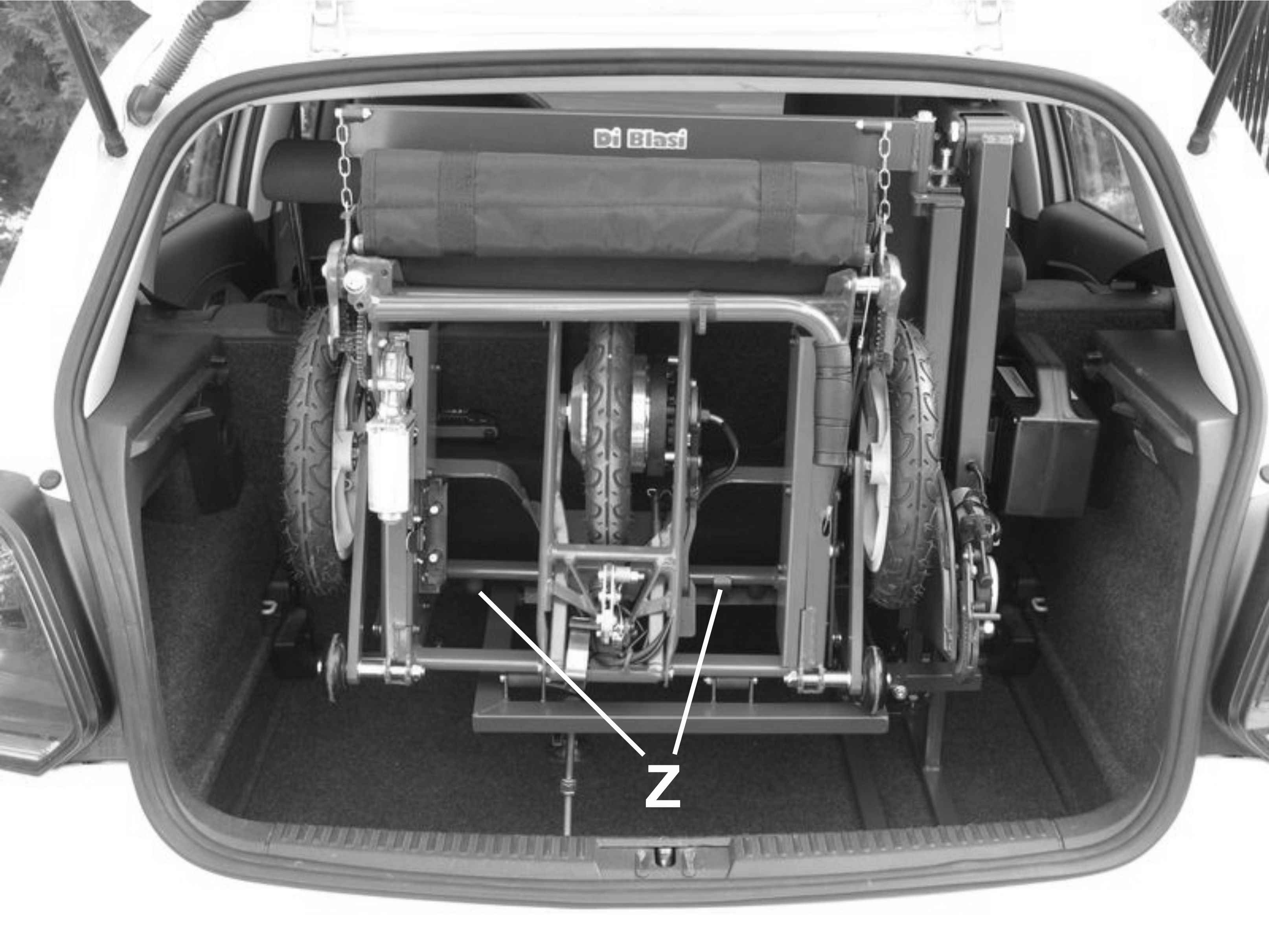
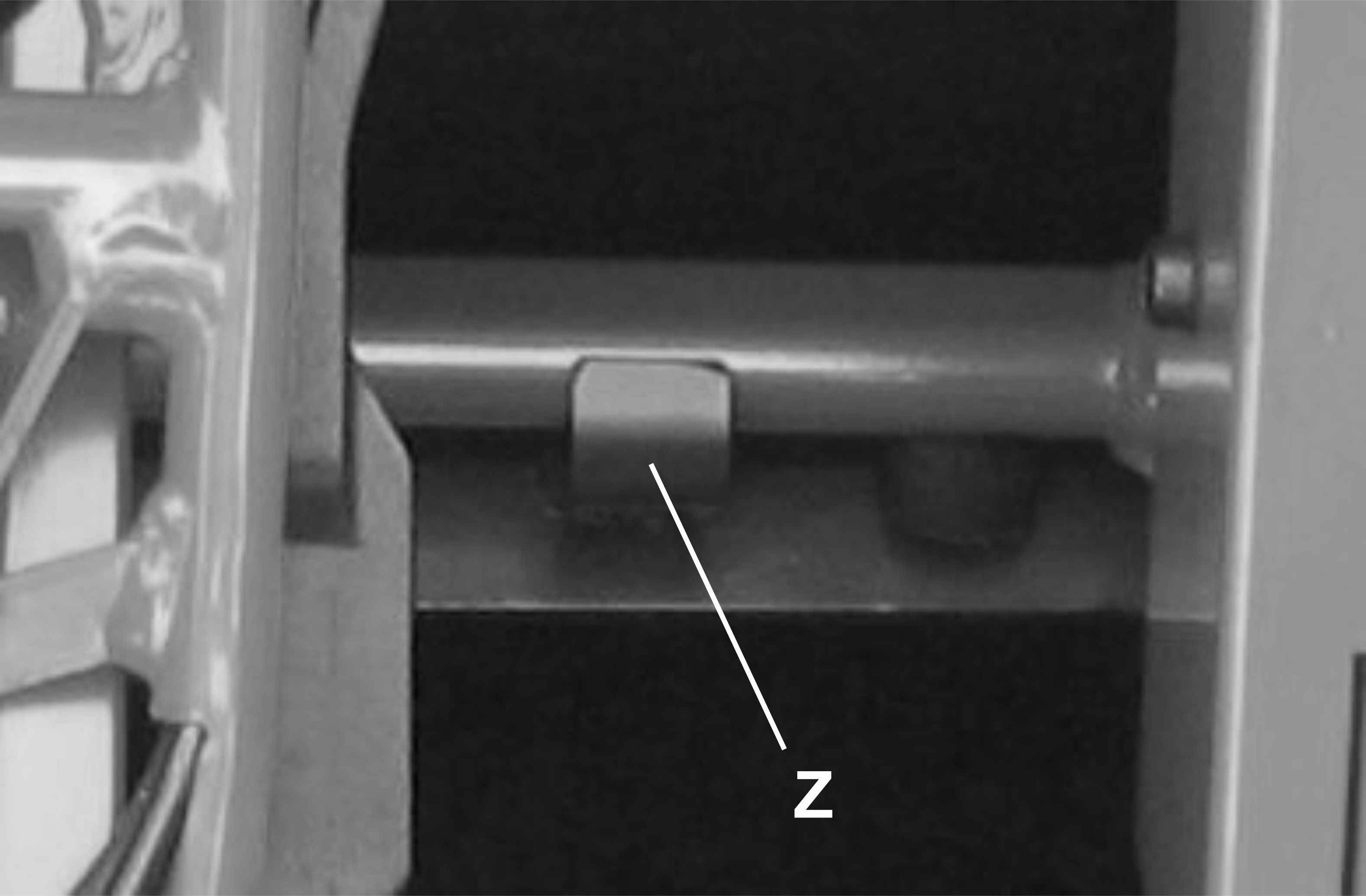
Press "arrow up" of the button (P) ( Img.75 ) until the lifting motor stops automatically, which occurs when the scooter is completely inside in the lifter ( Img.114 ). Check that that the tabs (Z) ( Img.115 ) secure the scooter to the lifter as shown in the picture. Shake the scooter a little bit back and forth to make sure that it is firmly blocked in the lifter.
TO UNLOAD THE SCOOTER FROM THE TRUNK
Important safety warnings
When loading and unloading the scooter, stay away as far as possible from the lifter ( Img.100 ).
When pressing the button (P) ( Img.75 ) ensure your fingers and the other hand are kept away from the surrounding area to prevent them from being pinched/injured in the lifting mechanism.
Keep loose clothing (such as ties, scarves, etc.) or long hairs away from the lifting mechanism as they could get entangled and you could be injured.
After having opened the boot door, press the "down arrow" of the button (P) ( Img.75 ) until the scooter rests on the ground and the lifter motor stops automatically.
Unhook the ring (L) from the pin (M) on both sides of the scooter
Move the lifter back into the boot by pressing the "up arrow" of the button (P) ( Img.75 ) until the lifter motor stops automatically.