FOR INSTALLATION AND USE
for mobility scooter
DI BLASI mod. R30
WARNINGS
The lifter is designed for loading or unloading from the boot of a car only the mobility scooter DI BLASI mod. R30. It must not be used for loading or unloading other items.
Do not modify the lifter in any way, as this can limit the safety of the product and invalidates any warranty.
Do not allow children to operate the lifter.
The manufacturer shall not be held liable for personal injuries and/or damages to the persons or to things that are a result of improper use of the lifter.
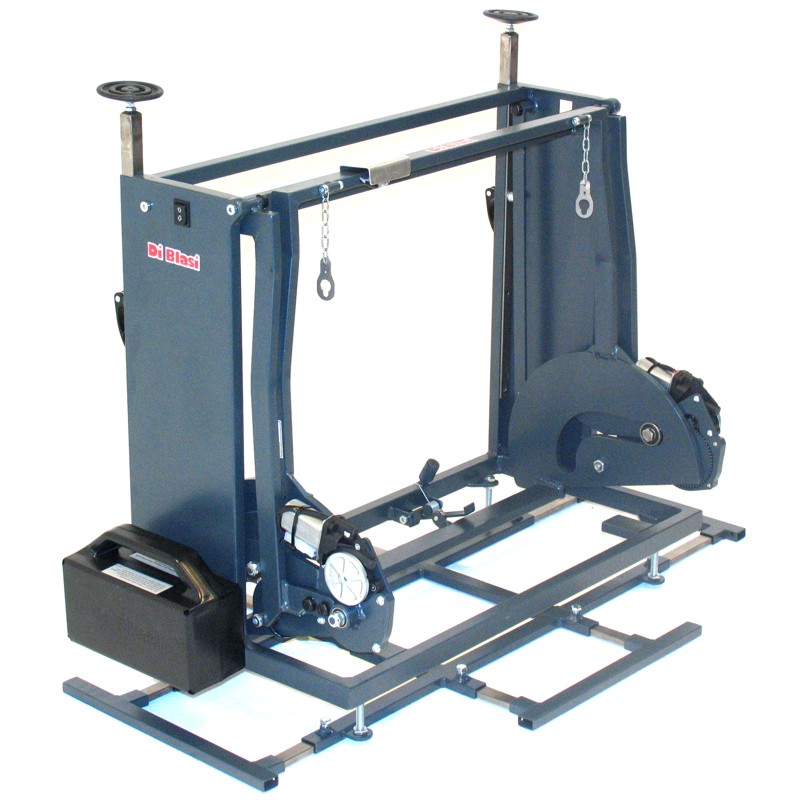
1) DESCRIPTION
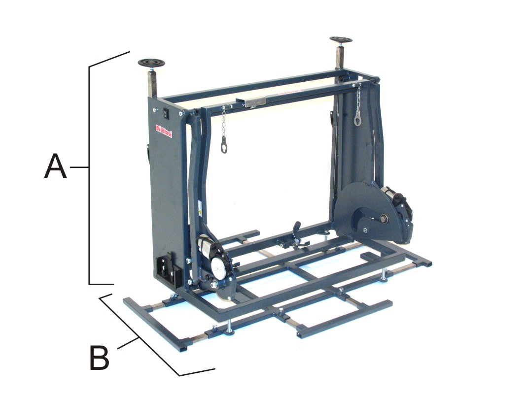
The lifter (Fig. 1) is essentially made of two parts:
The lift mechanism (A): it allows to automatically load on or unload from the boot of a car the scooter DI BLASI mod. R30.
The fastening frame (B): it allows to fasten the lift mechanism (A) to the floor of the boot and to adjust its height
The lifter is powered by two electric motors operated by the same battery of the scooter. Therefore the battery is not included in the standard equipment of the lifter.
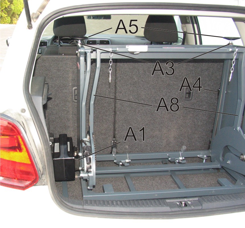
The lift mechanism (A) includes (Fig. 2):
The battery support (A1) on its left side
The operating rocker switch (A2)
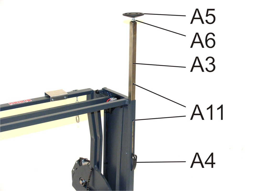
The vertical locking rods (A3)
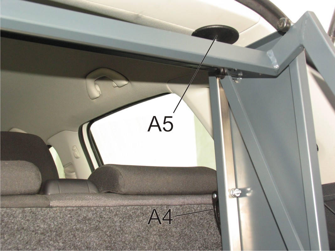
The quick release levers (A4)
The upper discs (A5) of the vertical locking rods
The moving arms (A8)
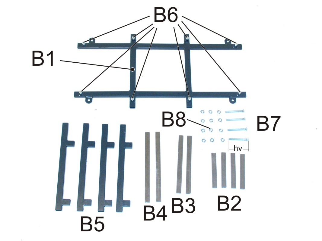
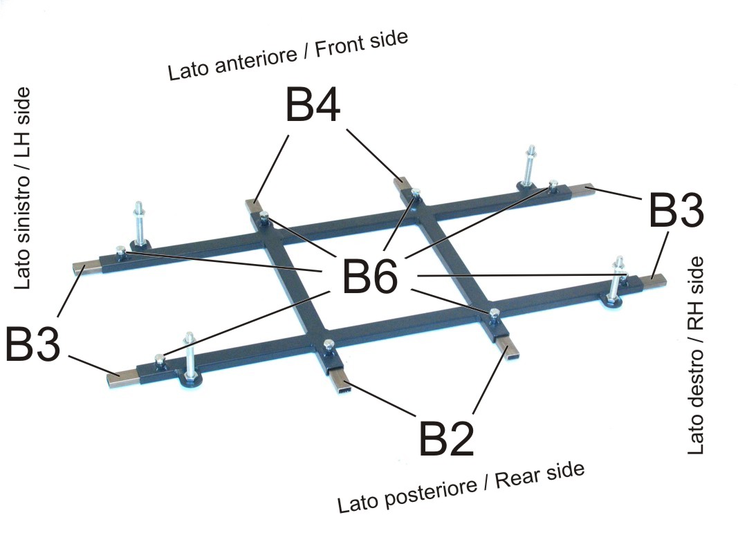
The fastening frame (B) is made of (Fig. 3)
The frame (B1)
2 struts (B2) (L= 15 cm)
4 struts (B3) (L= 25 cm)
2 struts (B4) (L= 30 cm)
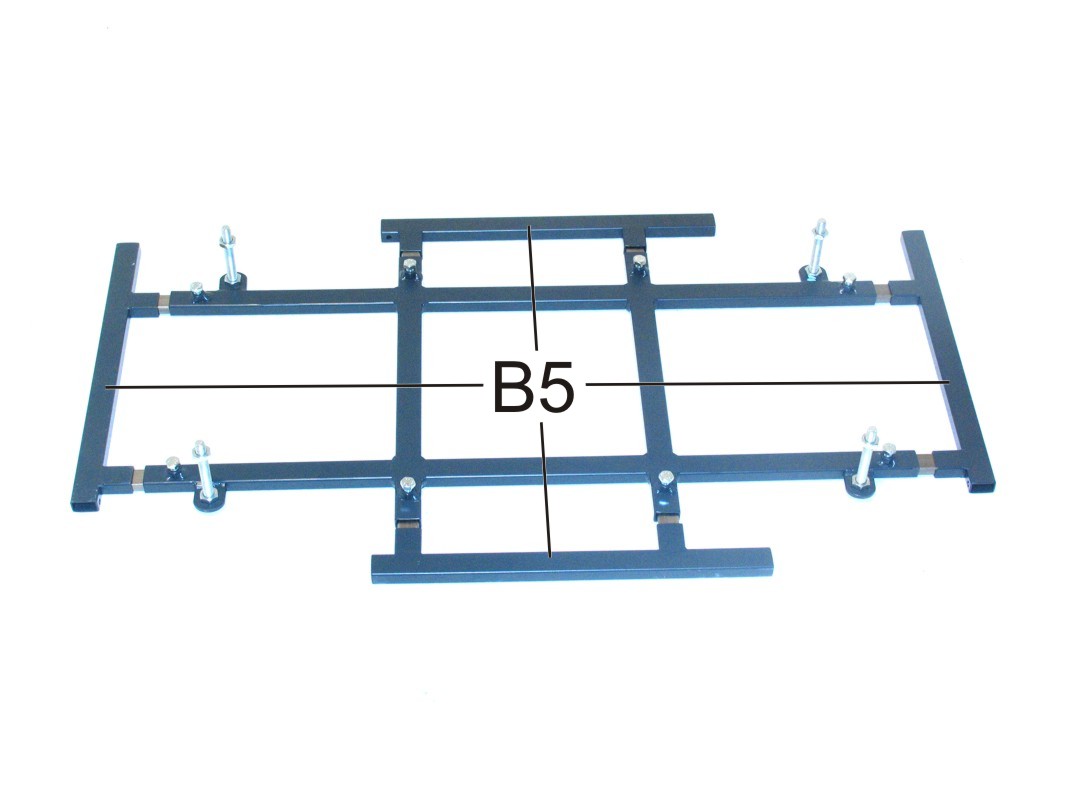
4 bumpers (B5)
8 screws (B6)
4 threaded rods (B7)
12 nuts (B8)
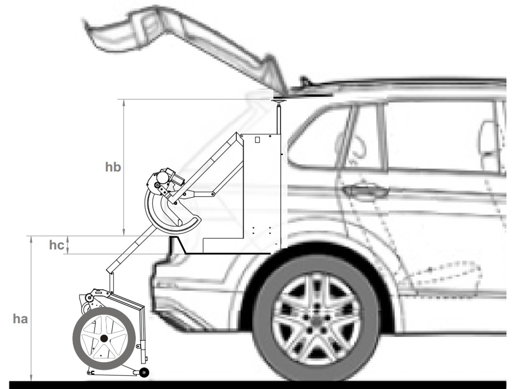
The rods (B7) are available in the following lengths (hv) (Fig. 3) according the height (hc) of rear edge of the boot (Fig. 7)
| (hc) (cm) | (hv) (cm) |
|---|---|
| 0-12 | 10 |
| 12-17 | 15 |
| 17-22 | 20 |
The
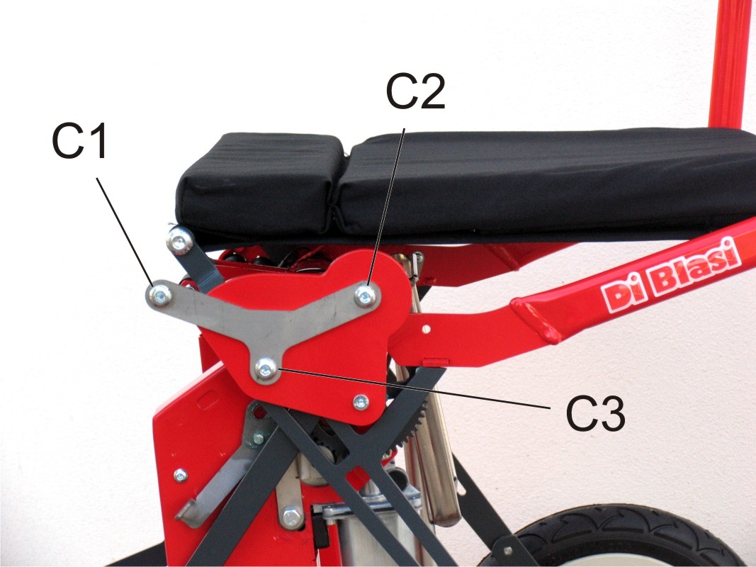
lifter includes also two lift brackets (C) (Fig. 4) to be fitted on
the scooter. They allow to hang the scooter to the lifter.
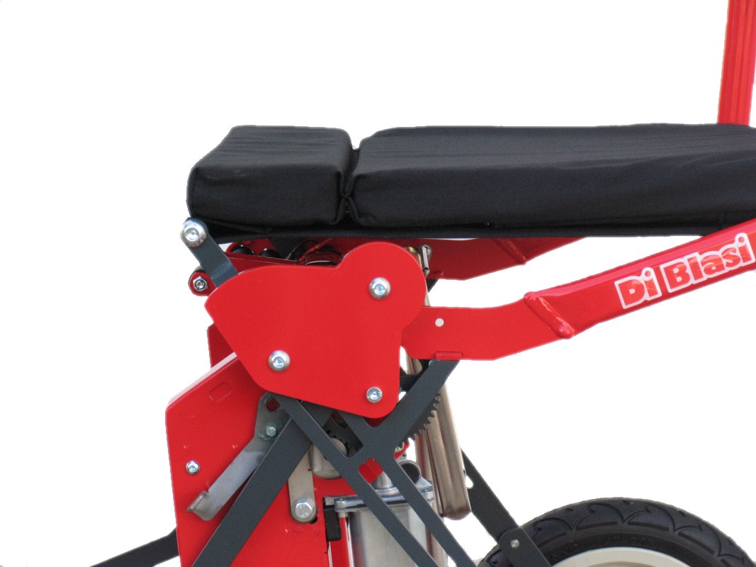
However
each variant of the scooter R30 requires its own bracket. Therefore
when ordering a lifter its is necessary to specify the variant of
the scooter. In this aim it is enough to send to the manufacturer a
picture of the side of the scooter similar to the picture shown in
(Fig. 5)
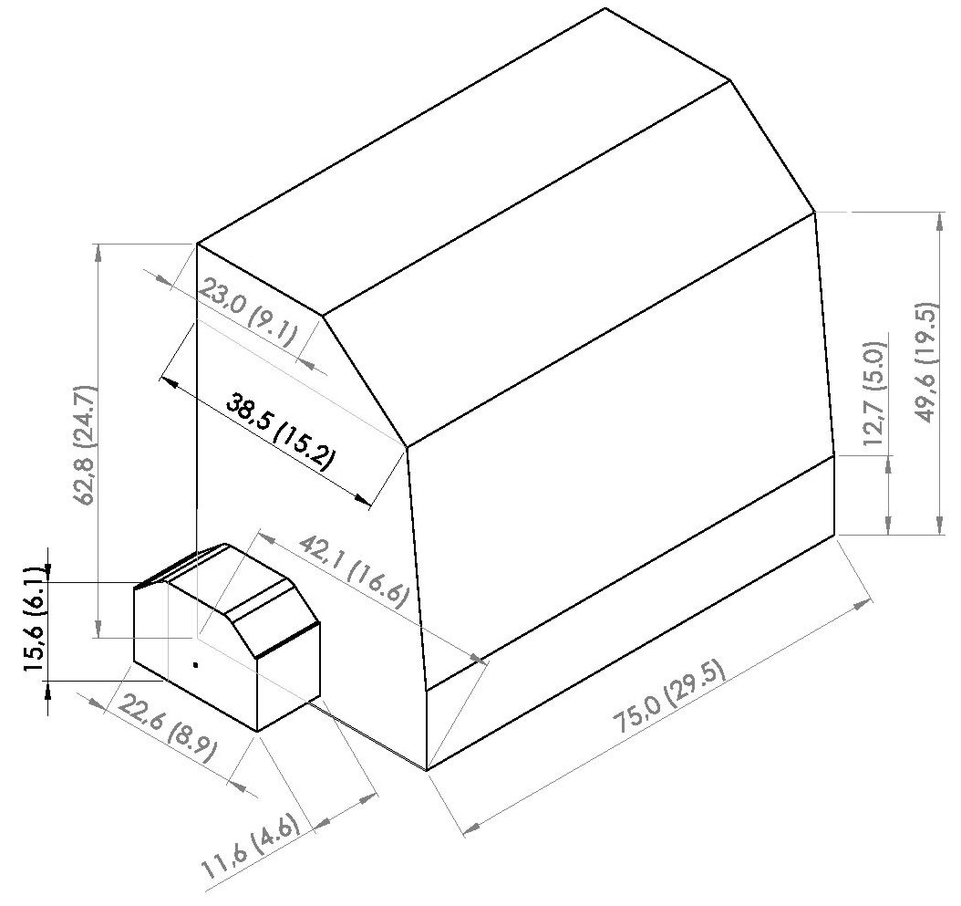
2) SPECIFICATIONS
Dimensions: see (Fig. 6)
Weight (without battery): 27 kg (approx)
Weight of the battery: 3 kg (approx)
Motors: 2 at 24V
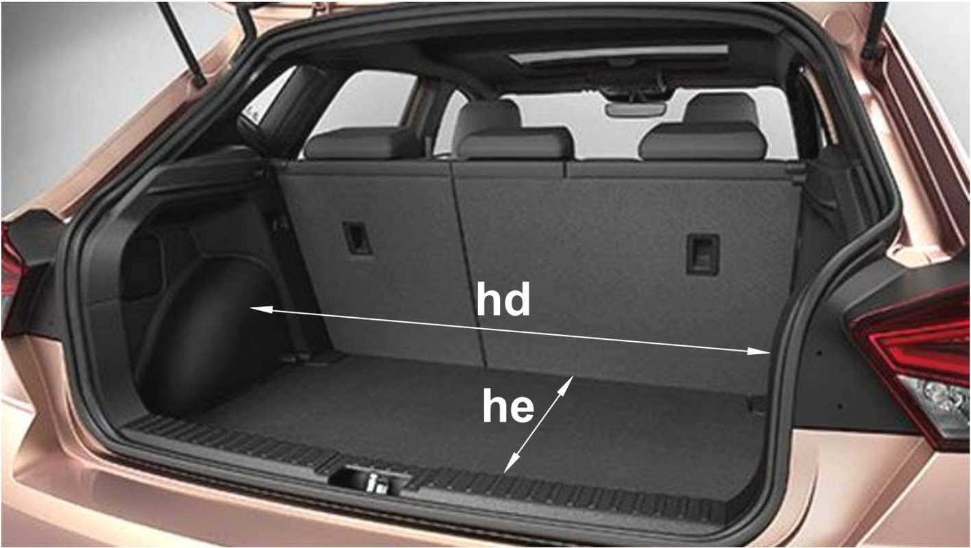
3) REQUIRED BOOT DIMENSIONS (Fig. 7) (Fig. 8)
ha = 75 cm (29,5 in) maximum
hb = 64 cm (25,2 in) minimum)
hc = 0 - 200 mm
hd = 90 cm (35,5 in) minimum - 120 cm (47 in) maximum
he = 52 cm (16 in) minimum - 84 cm (33 in) maximum
On demand the lifter can be supplied made fit for boot having:
ha = 82.5 cm (32,5 in) provided hb = 68cm (27 in) minimum
or
ha = 90 cm (35,5 in) provided hb = 72cm (28,5 in) minimum
On demand the struts (B2) (B3) (B4) (Fig. 3) can be supplied with lengths suitable for dimensions (hd) and/or (he) greater than the above maximum ones: in this case the customer should specify the dimensions (hd) and/or (he) of the boot of his car.
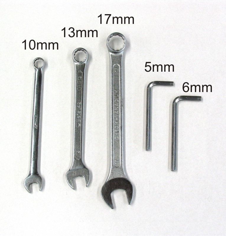
4) TOOLS NECESSARY FOR ASSEMBLING THE LIFTER (Fig. 9)
Hexagon wrench 10 mm
Hexagon wrench 13 mm
Hexagon wrench 17 mm
Allen wrench 5 mm
Allen wrench 6 mm
5) INSTALLATION OF THE LIFTER IN THE BOOT
Assembling to be carried outside the boot
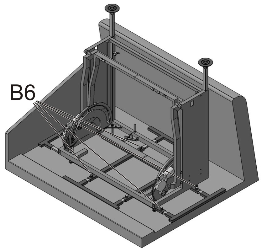
Put the frame (B1) on the assembling bench with the 8 screws (B6) in upward position (Fig. 11). Let consider as rear side any of the two longer sides; therefore the RH side and the LH side shall be the shorter sides respectively at RH side and LH side of the operator when facing the rear side.
Determine the necessary length of the threaded rods (B7) depending on the height (hc) (Fig. 7) of the rear edge of the booth and according to Tab. 1 at Chap 1
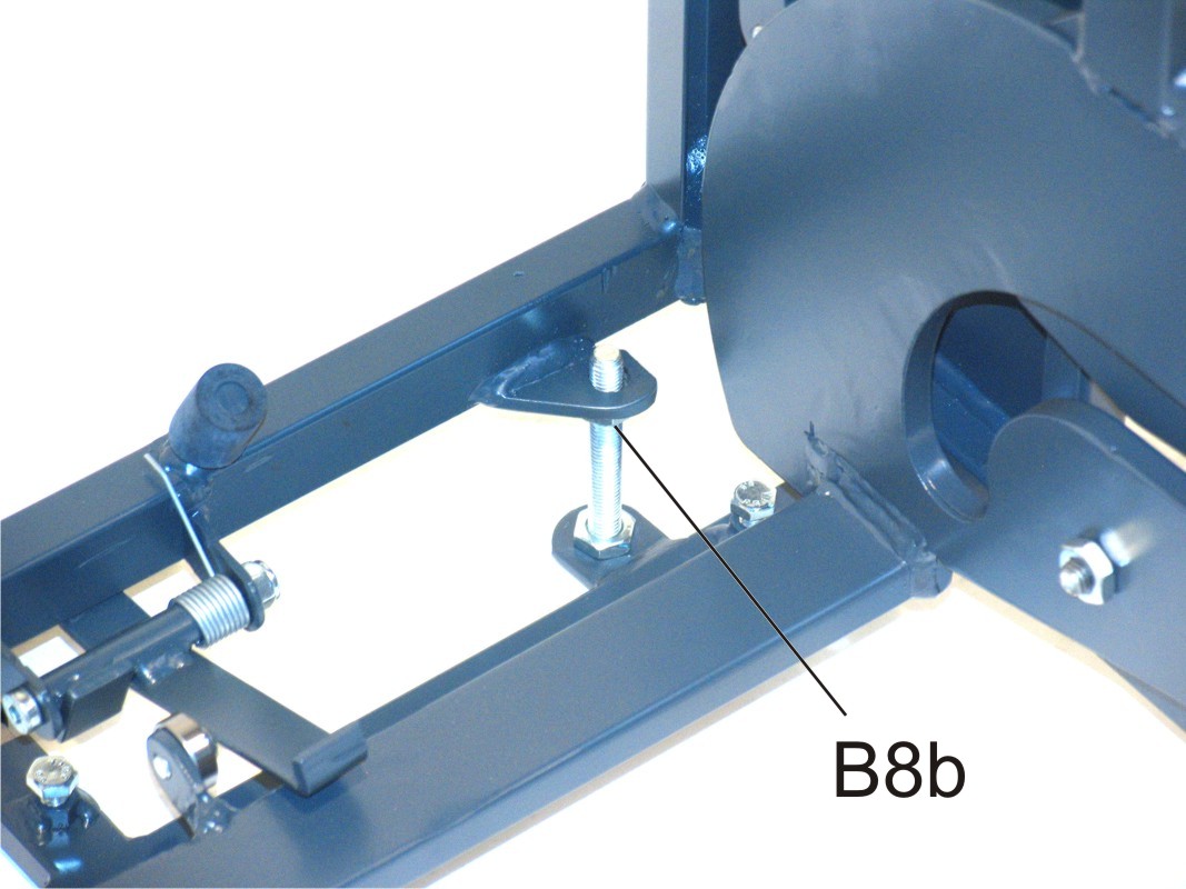
Fit the 4 rods (B7) as shown in (Fig. 11) and in detail in (Fig. 10):
Fit each rod upwards and lock it using a nut (B8a)
In
each rod screw a nut (B8b) until that the distance (hm)
from the upper side of nut (B8b) and the bottom side of
the frame (B1) is:
Fit two struts (B2) (L=15 cm) inside the two rectangular tubes on the RH side of frame (B1) but leaving about 4 cm not inserted. Tighten slightly the relevant screws (B6) (Fig. 11)
Fit two struts (B2) (L=15 cm) inside the two rectangular tubes on the rear side of frame (B1) but leaving about 4 cm not inserted. Tighten slightly the relevant screws (B6) (Fig. 11)
Fit two struts (B3) (L=25 cm) inside the two rectangular tubes on the LH side of frame (B1) but leaving about 4 cm not inserted. Tighten slightly the relevant screws (B6) (Fig. 11)
Fit two struts (B4) (L=30 cm) inside the two rectangular tubes on the front side of frame (B1) but leaving about 4 cm not inserted. Tighten slightly the relevant screws (B6) (Fig. 11)
Insert a bumper (B5) at the end of each couple of struts (Fig. 12). Place the longer side of the bumper as more convenient according to the shape of the boot.
Assemble the lift mechanism (A) on the fastening frame (B)
The rear side of the lift mechanism (A) (i.e. the side where the two hanging chains are located) must correspond to the rear side of the fastening frame (B)
Put
the lift mechanism (A) on the top of the fastening frame (Fig.
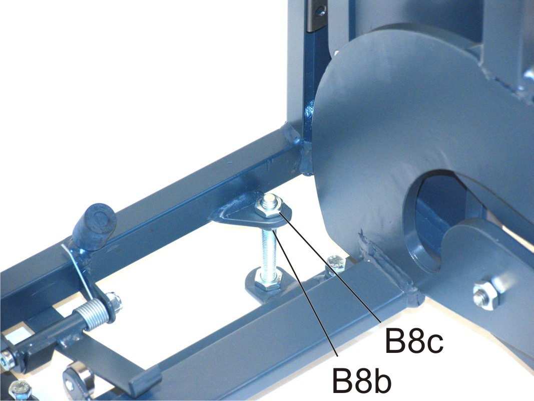
13). Insert each of the 4 struts (B7) of the fastening frame in
the correspondent hole (A9) at the lower part of the lift
mechanism (Fig. 13) so that its bottom side rests on the upper
side of the nuts (B8b) (Fig. 14).
(Two persons are necessary
to carry out this operation).
On the top of each strut (B7) screw a nut (B8c) (Fig. 15) and tighten so that the lift mechanism (A) and the fastening frame (B) become integral
Fitting of the lift brackets (C) on the scooter (Fig. 4)
Remove the screw (C2) from the scooter (Fig. 30), place the bracket (C) as shown in (Fig. 30), screw the screw (C2) without tightening. The round head of the screw (C1) must remain on external side.
Remove the screw (C3) (Fig. 31).
Move the bracket so that its remaining hole corresponds with that of screw (C3), then screw again screw (C3)
Tighten the screw (C2)
Fit the bracket (C) on the other side of the scooter
Assembling to be carried inside the boot
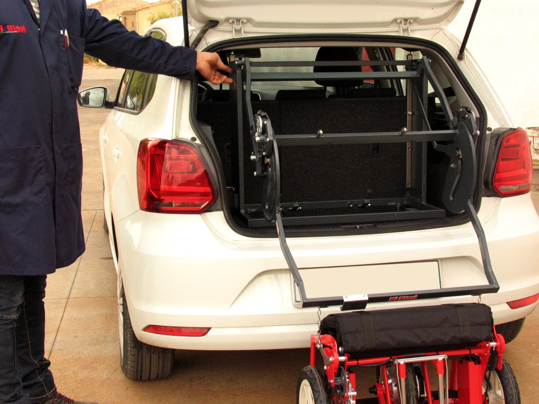
Two persons are necessary to load the lifter in the boot of the car (Fig. 20). If the boot is not deep enough, lower the back of the rear seat and then, if possible, raise it after that the lifter has been installed.
Adjust transversally the position of the lifter so that:
Adjust longitudinally the position of the lifter so that:
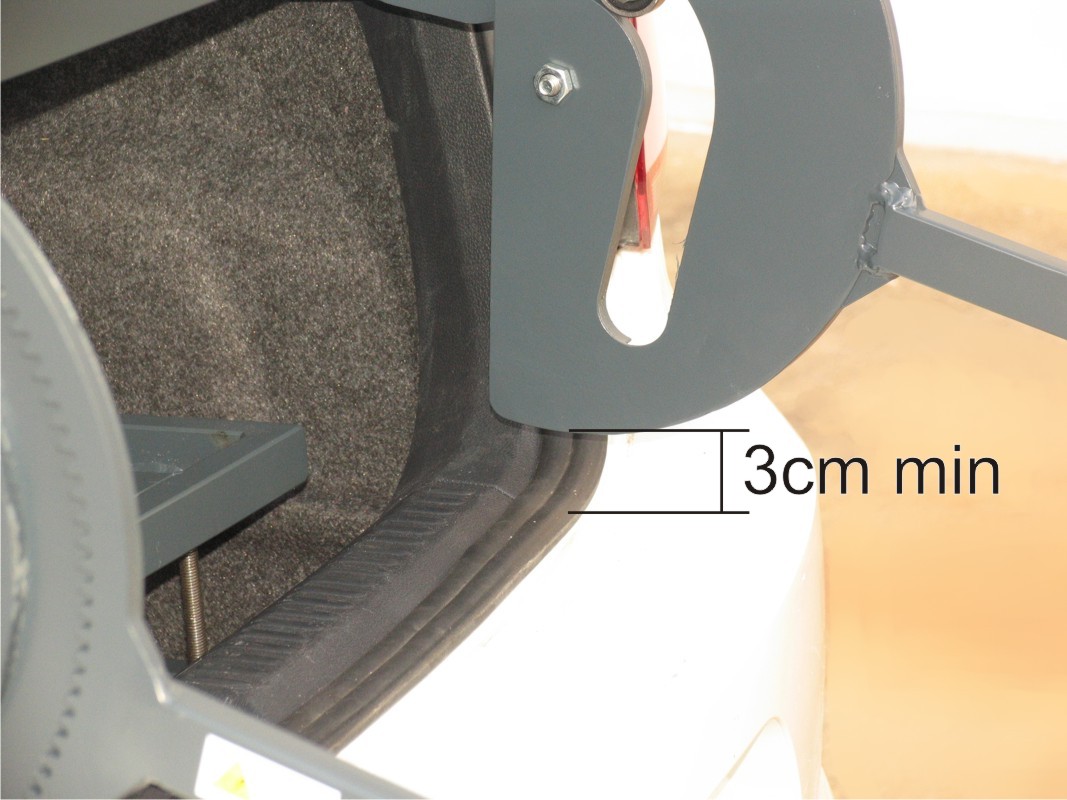
The rear side of the lifter shall not interfere with the boot door and in particular with its window: leave at least 3 cm gap between the rear end of the lifter and the window.
The position of each of the two discs (A5) corresponds to an almost horizontal area of the roof where they shall come in contact after that the vertical rods (A3) shall be raised (Fig. 21).
Loosen the 8 screws (B6) of the fastening frame and, without moving the lifter from its position, extend all struts (B2), (B3), (B4) so that each bumper (B5) comes in contact with the relevant side of the boot (Fig. 22).
Tighten the 8 screws (B6)
Raise the quick release lever (A4) located one of the front corners of the lifter, raise the relevant locking rod (A3) (Fig. 23) until that the disc (A5) comes in contact with the roof (Fig. 25), pull down the quick release lever (A4) so to lock again the vertical rod (A3). The clamping of the quick release lever can be adjusted like that of the bicycles seat post quick release levers.
If the maximum upper position of the rod (A3) is not enough to put the disc (A5) in contact with the roof, remove the quick release lever (A4) and insert it in one of the lower holes (A11) of the rod (Fig. 23).
Check if the nut (A6) is tightened against the upper end of the rod (A3): if this nut is not tightened, the screw supporting the disc (A5) could rotate so that the disc could loose the contact with the roof (Fig. 23).
Carry out the same operation with the rod (A3) located on the other front corner of the lifter,
Push and pull by hand the lifter transversally and longitudinally so to check that it is firmly fitted on the boot.
Insert the battery in its support (A1) (Fig. 21).
Close and open the door of the boot very carefully and very slowly and check that it does not come in contact with any part of the lifter and that there is at least 3 cm gap between the rear end of the lifter and the window.
Press "arrow down" of the switch (A2) (Fig. 2) with very short impulses and at each impulse check that any moving element of the lifter comes in contact with any part of the boot. In particular check that the lower side of the semicircular element remains always at a distance of not less than 3 cm from the upper side of the boot edge (Fig. 24). If this distance is less than 3 cm, recover the missing distance as follows:
Drive the car for a short trip including curves and brakings and then check if the lifter remains firmly blocked in the boot.
Load the scooter in the boot (see Sec 6) and drive the car for a short trip including curves and brakings and then check if the lifter remains firmly blocked in the boot and if the scooter remains firmly blocked inside the lifter.
6) OPERATING INSTRUCTIONS
Loading the scooter in the boot
IMPORTANT SAFETY WARNINGS:
During loading and unloading of the scooter stay away from the lifter as much as possible (Fig. 40)
When pressing the switch (A2) (Fig. 2) ensure your fingers and the other hand are kept away from the surrounding area to prevent them from being pinched/injured in the lift mechanism.
Do not allow loose clothing e.g ties/scarves or long hair to hang near the lift mechanism.
Insert the battery in its support (A1) (Fig. 21)
Extend completely the lift arms by keeping pressed "arrow down" of the switch (A2) (Fig. 2)(Fig. 40)
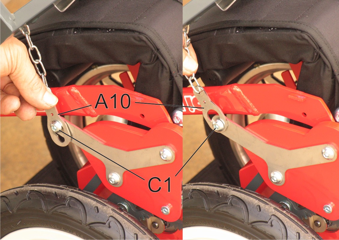
Fold the scooter and place it so that the back rest faces the boot and so that the rings (A10) at the bottom of the two chains of the lifter come near the hooking pins (C1) (Fig. 31) on the sides of the scooter (Fig. 40)
In both sides of the scooter hook the ring (A10) at the hooking pins (C1): insert the pin (C1) in the larger part of the hole of the ring (A10) and then move the ring so that it ring cannot come out from the pin (C1) as being prevented by the narrow part of the hole (Fig. 41).
Press shortly "arrow up" of the switch (A2) (Fig. 2) until that both lift chains become tight, then check that each ring (A10) is blocked on the relevant pin (C1) by its narrow part of the hole.
Press "arrow up" of the switch (A2) (Fig. 2) until that the the scooter remains completely inside the lifter and the lift motors stop automatically. Check that the scooter remains blocked in the lifter by pushing it a little bit forward and rearward.
Unloading the scooter from the boot
IMPORTANT SAFETY WARNINGS:
During loading and unloading of the scooter stay away from the lifter as much as possible (Fig. 40)
When pressing the switch (A2) (Fig. 2) ensure your fingers and the other hand are kept away from the surrounding area to prevent them from being pinched/injured in the lift mechanism.
Do not allow loose clothing e.g ties/scarves or long hair to hang near the lift mechanism.
After having opened the door of the boot, press "arrow down" of the switch (A2) (Fig. 2) until that the scooter rests on the ground and that the lift motors stop automatically (Fig. 40).
Disconnect the rings (A10) from the pins (C1) (Fig. 41)
Draw back the lifter inside the boot by pressing "arrow up" of the switch (A2) (Fig. 2) until that the lift motors stop automatically.
If necessary, remove the battery from the support (A1) (Fig. 21) and use it for riding the scooter.